Scratchbuilding, page two.
Starting with Axels and following up on some suspension, engine tips this page will help you get to grips with some of the more 'worrying' areas that might put some people off. Keep at it you'll surprise yourself with what you can achieve.
Axels, springs and shackles,
.......look complicated but for the most part are straight forward. Study the plans and photo’s, look for the shapes within the axel and then make the shapes.
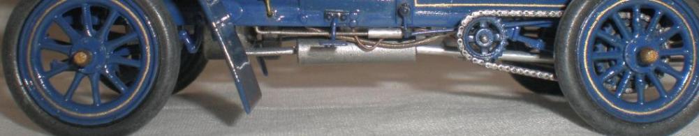
Below is the offset drive line of the 1904 Darracq. Similarly made from tube and rod, in the picture it is easy to pick out the shapes and method of construction.
For I beam axels make the main beam shape then cap it with strip. Half round strip at the ends simulates the kingpin housing. A little sanding finishing gives you your basic axel.
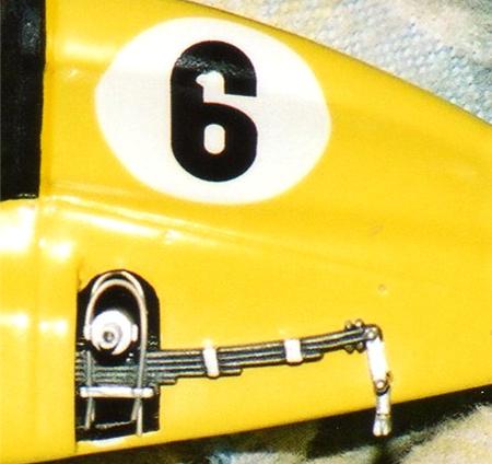
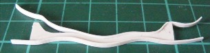
As can be seen here leaf spring can be made from plastic strip cut to the appropriate lengths. The problem comes in inducing the correct angle of bending so to start with we simply secure the leaves to a central pin. This can also locate the shackle plates ensuring these are central too.
Once the chassis and axel are ready to accept the springs then the angle of bend can be put in and the spring leaves secured with liquid cement.
The shackle bolts are simple plastic rod, secured with cement, and then trimmed and sanded leaving a bolt head to paint.
Spring shackles are straight forward to build. Cut a length of strip to the required size. Drill four holes in it then feed some wire over the axel and through the holes in the plate. Nut heads can be made from cored hex NBW sets, photo etched sets or punched out of plastic card using a punch and die set.
These ones just need pulling tight and securing with super glue.
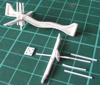
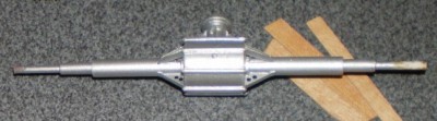
Below is the rear axel and diff’ from a 1/16th scale Itala (a real long term project) made simply from lengths of plastic tube, rod, card and strip. Model Dr nuts and bolts add the final details and set off the part. The difficulty with this is keeping the axel centred in the larger diff’ housing. This is best done by cutting out the discs with a compass cutter which automatically gives you a central point. You just need to take your time enlarging the hole till the central axel can be put through. After that the larger tubes were added over this providing not only the shaping but also strength.
The triangular strengthening parts were cut from strip and drilled out for weight reduction, capped with thin strip which had to be shaped to fit around the tube of the axel housing.
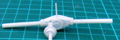
On the left is the diff’ from a Model T speedster. It was made in a different way. For this job half of the diff’ case was turned on a lathe and then moulded so two identical halves could be cast in resin and put together, in similar fashion to the real cars cast metal casings.
Being a more expensive and advanced form of scratch building we wouldn’t recommend you start with this system but it is something to work up to as it can save time and ensure you get symmetrical parts for both sides, or ends, of a car.
You probably don’t have a lathe either but you can start by turning rod and tube in any mini-motor tool to give shaping to the ends of drive shafts and other parts. Don’t try anything to ambitious to start with just work your way up.
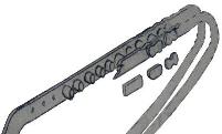
As shown earlier leaf springs are straight forward to make but connecting them to the chassis requires some shackle links. From this photo you can see the steps to making them and the rear dumb irons. Once again rod and tube prove effective, as does strip and a good drill bit set.
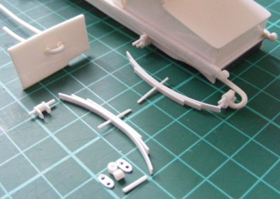
The dumb irons have been formed by passing the rod through the holes in the card and repeatedly warmed and pulled in tighter. If you rush this, introduce glue to soften the plastic or direct heat, the plastic will almost certainly break or deform. Once the required shape is achieved it is no problem to cut and sand the part to its final shape.
The important thing to say here is that this work is not that hard, you just have to take your time.
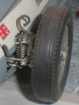
The suspension on the Maserati 250F was all scratch built using fuse wire, rod and tube. Plastic tube and rod make acceptable shock absorbers which can be improved further if you are prepared to try turning the tube in a mini motor tool (Dremel, Minicraft etc). The coil spring itself is simply fuse wire wrapped around a plastic tube of same diameter as the shocker.
Drive chains.
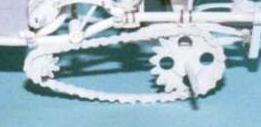
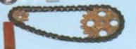
In large scale chains can be made of individual links just like the real thing. This is a time consuming process of cutting ‘Evergreen’ strip into the same size lengths and then sanding each one into an hourglass shape. In order to simplify this process the inner rows of the chain links can be cut in two rings from a flat plastic card of the same thickness as the strip. This gives the advantage of shaping the droop of the chain while adding strength to the assembly. The individual links made from strip are added to the outside of the ‘rings’ which are then shaped to represent the inside links, more time consuming than difficult.
The rollers can be cut from rod but are easier to make if you can punch them from strip or sheet using a Historex round punch and die set.
In 1/24th. and smaller scales strips of corrugated plastic will suffice.
Drive chains look difficult but are mostly just time consuming and fiddly.
The sprockets for the drive system are made using simple school geometry and drawing skills. The main thing is to take ones time in marking out and preparing before cutting. Having fixed the positions of the power and drive shafts the distance between them can be measured and the chains made.
Conical parts.
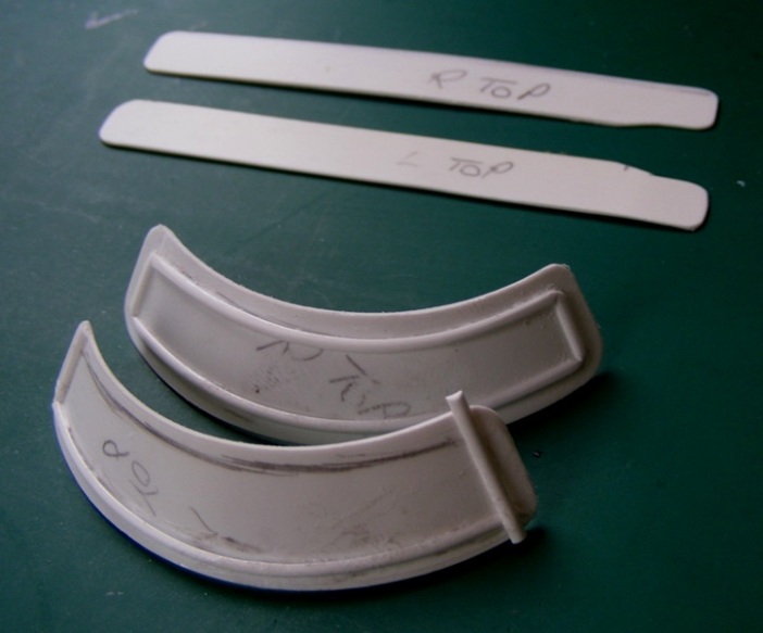
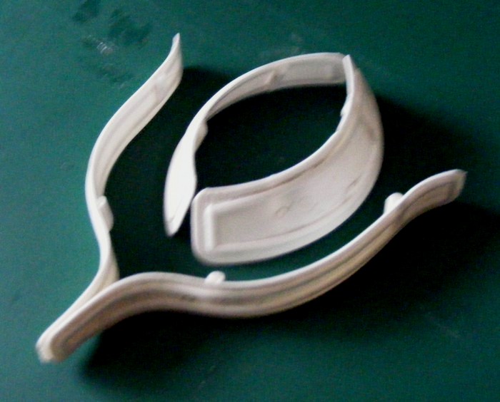
Moving on to parts that attach to the chassis, and that are often tricky to make, we will take a look at making wings. Below are photo’s of the 1904 Darracq front and rear wings. The rear only move through one plane so its a straight forward matter of shaping the plastic as outlined earlier, but the front wings are curved and angled posing a difficult problem for modellers. However Rod has recorded his system for making cone shapes which he used to make these wings.
Note also the typical period strengthening replicated by use of half round Evergreen strip.
MAKING CONES AND TAPERED STRUCTURES FROM FLAT SHEET PLASTIC
Every modeller can make angular structures such as boxes, and pyramids from flat plastic sheet but when it comes to making conical and tapered structures from sheet material then that is a different matter. The problem is the transposing to a flat sheet surface a shape that has to have a curved and tapered form to obtain the level base for it to have the correct stance. Usually I have resorted to making paper patterns and cutting them out and amending them until I get the curve right. There must obviously be a mathematical formula for this problem but so far it has eluded me. However, I have now devised a system for drawing templates to make conical structures and having spent some considerable time solving the problem I knew I would never remember how I had done it unless I wrote it down for future reference. It does work but you may have to make a few minor adjustments to get it just right. The advantage is that you can draw a template on paper or card, then cut it out and form it to shape to check its accuracy and make any necessary adjustments before committing it to plastic sheet. Refer to the diagrams as you follow the instructions.
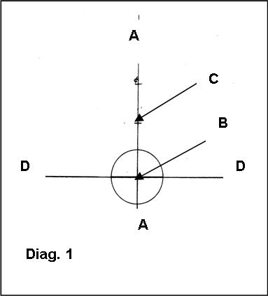
1. Diagram 1. Draw a vertical centre line ‘A–A’.
2. Mark on the centreline at convenient positions the base point of cone, ‘B’ and then mark the top of cone ‘C’ at the height you require the structure to be.
3. Draw with a compass a circle the diameter of the base centred on mark ‘B’. Now draw horizontal line ‘D–D’ through the centre point and extending well beyond both sides of the circle.
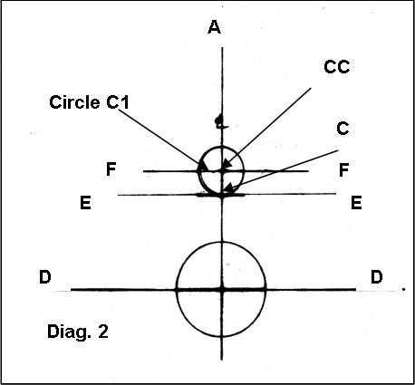
4. Diagram 2. Draw a horizontal line ‘E-E’ through mark ‘C’. Set your compass to the radius (not the diameter) of the cone top. Place the compass point on mark ‘C’ and draw an arc mark above on centre line ‘A-A’ (mark ‘CC’). Place point of compass on new mark ‘CC’ and draw circle ‘C1’. Now draw horizontal line ‘F-F’ through the centre of circle ‘C1’.
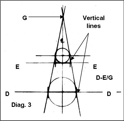
5. Diagram 3. Draw a vertical line at the edges of circle ‘B1’ to bisect line ‘D–D’, and also at circle ‘C1’ to bisect line ‘E–E’. NOTE. Make sure you place bisect marks on line ‘E-E’ and NOT line ‘F-F’.
6. Draw connecting lines between these ‘bisect marks’ to provide two lines ‘D–E’ and continue these lines upwards until they bisect the centre line at mark ‘G’. You now have a side elevation of the cone you require bordered by the lines ‘D–D’, ‘E–E’ and tangent lines ‘D-E’. This is a useful guide to check that you have the shape you want.
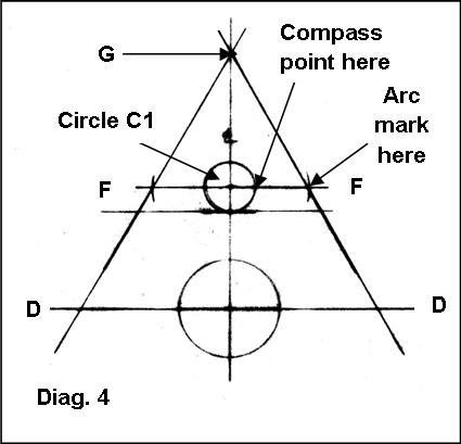
7. Diagram 4. Set your compass to the diameter, NOT the radius of circle ‘C1’ and then position the compass point on the circumference of circle ‘C1’ where it bisects line ‘F-F’ and draw an arc to bisect line ‘F’ at its extremities. Do this on both sides of circle ‘C1’.
8. Draw two lines from mark ‘G’ through the ‘arc marks’ just made on line ‘F-F’ and continue on to bisect the line ‘D–D’.
9. Place the compass point at ‘G’ and set the compass to reach the mark point ‘C’ and draw an arc spanning the two tangent lines drawn in step 8. With the compass point still on mark ‘G’ but reset to reach mark ‘B’ draw a second arc spanning the two tangent lines drawn in step 8.
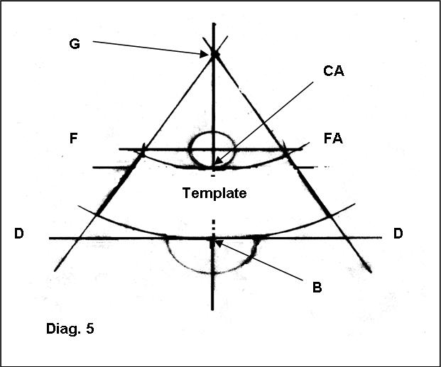
10. Diagram 5. You now have a curved template bordered by two arcs, one spanning line ‘F-F’ and the other passing through the centre of circle ‘B1’ and the two tangent lines each side extending from line ‘F-F’ to the arc passing through mark 'B'.
Engines.
Scratch building engines is probably the most daunting task in any project. Just looking at an engine throws a kaleidoscope of shapes and patterns at your eyes. So the first point, is do you need to make and engine at all. For many model cars the engine is hidden within the cars body work and will seldom, if ever, be seen. ‘Curbside’ models or ‘slammers’ are perfectly acceptable. Not every model is a super detailed competition winning car, this is a hobby and scratch building is an extension of the hobby so we can have the cars we want in our collection, even if there isn’t a kit available.
If you decide you have to have an engine, don’t worry, the process is just the same as for any of the other parts we have already described. It make take a little longer to break down in your mind but simply look for the basic shapes and build them up from the inside out. It may help you to sketch out the shapes in order to plan your build.
A simple tube for the crank case can be split by the addition of strip for the flanges. Add it all round, sand to shape and use hex nbw’s to detail.
Set 1,2,4,6 tubes atop the crank case and then think of tubes for the exhausts and intake sides.
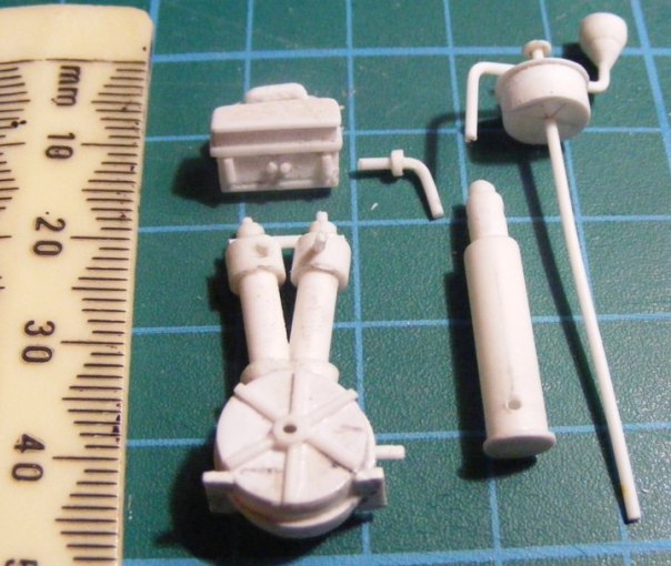
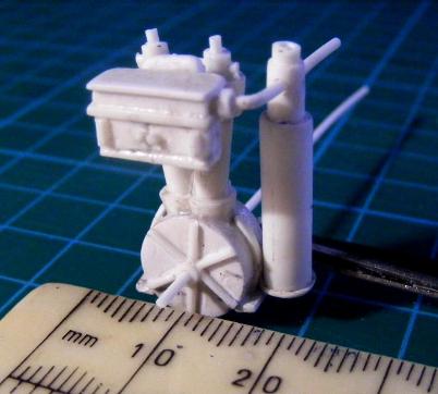
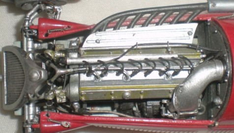
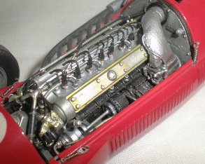
Taking the idea of seeing the shapes and building them, here is the Daimler Phoenix engine used in many early vehicles.
These photo's shows how the engine was built from plastic rod and strip. It may be time consuming and need some practice but it is not difficult to do.
The same basic idea can be used for cylinders or, depending on the era, cylinder blocks. You build up the shape and add the details you can see. With the evergreen range of plastic rod and strip you can slide different sizes inside one another in order to make flanges for cylinders or exhaust headers.
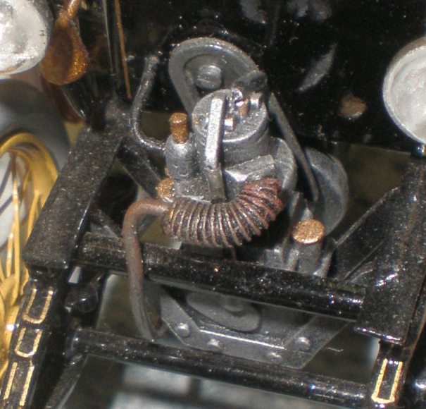
These 'blown up' finished build photos of the Renault type 'A' engine (basically still a Daimler engine) show more clearly where shapes have been added over the base block, and how the simple procedure can be very effective. Other items like the cooling vanes on the exhaust pipe are 5 amp fuse wire wrapped around tube, cored with copper wire. Drybrushing picks out the high points making the effect more realistic. More recently soft resin cooling hose can be bought from ‘Renaissance’ in France, and photo etch shape sets can make this process even easier and better looking.
Of course how accurate and detailed you want to be remains in your hands. This is a hobby and at first the sense of achievement from scratch building even a simply model is great and you should be rightly proud of your efforts, whatever anyone else says. Over time you gain experience and confidence and your skills improve just like when you first started model making.
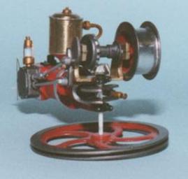
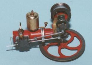
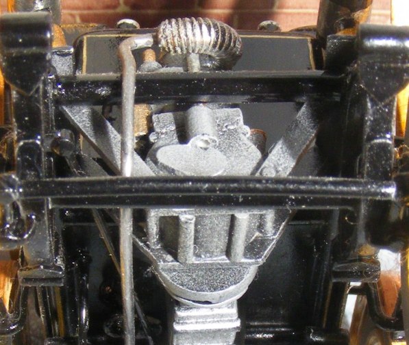
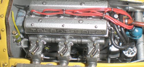
The scratch built Panhard’s engine, left, is further example of the principles, while on thr right is the workings of an 1888 de Dion steam car.
Once you have a basic engine you need to scratch build hoses, wiring and other detail parts for it.
These photos of the finished Benz prototype engine show the same ideas in use, building up shape upon shape while making use of any items that can be found around the house. I don’t want to over simplify the process or reduce the kudos scratch building rightly has, but at the same time you should be encouraged to have a go.

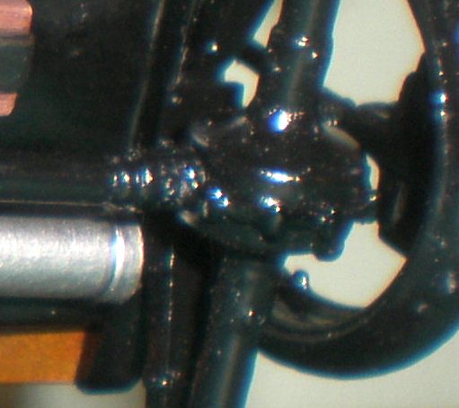
Wiring and hoses.
Simple wiring in of the distributor to the spark plugs is the first step. From there you will probably want to add the rest of the wiring system and brake and hydraulic lines, both fixed and flexible.
Many products are now available to help you. Photo etched wiring looms and blocks, heat shrink plug boots and painted wire as well as plastic covered wire in loads of colours and sizes can all be of use. However, these can be expensive, and you may well be able to use house hold items or make your own parts.
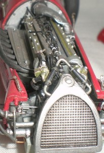
As you can see some wiring and hoses go a long way to breathing life into a model. How accurate and detailed you want to be will depend on you and your references.
The key of wiring and plumbing is the fixing of the hoses or wires in place. Big blobs of superglue don’t look very realistic. Our tip for keeping wiring ‘clean’ is to drill deep holes so the wire has plenty of room to grip low down rather than on the surface. Use clear varnish rather than super glue, it not as fast ‘grabbing’ but is much cleaner. Pre-shape the wire or piping to go where you want first, rather than glue one end then try shaping the wire, trying to shape the wire after fixing almost always ends in pulling the wire out again!
When using tube it is often a good idea to put wire through it to stop it collapsing in the bends, the wire needs to be thick enough to fill the tube but not to make the tubing stretch. Sometimes the wire itself can be used as the point of attachment to the radiator or pump, so the hose looks like it has been slid onto the pipe. A simple jubilee clip can be fashioned from 5amp fuse wire or you can invest in photo etched hose clips. This depends on the era of the model.
For secured hoses hex fittings, usually white metal or turned aluminium, are the best but you can use a Historex punch and die set to make these, with just a little drilling and shaping you can make hose fittings for a fraction of the cost.
Scale need not be a barrier to detailing, the larger the scale the easier it is to work on but the more there will be to see.
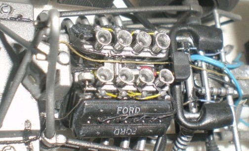
Above is the 1/32nd scale Matchbox Tyrrell engine. Using painted 5 amp fuse wire and thin plastic coated wire, elastic and masking tape the model was brought to life. The key is careful use of a very sharp knife blade to mark the starting point of the drill bit. With a small hole to start the drill bit off it is more likely to stay were you want it and not slip off to the side. Of course a good set of drill bits and a good quality hand drill (or pin vice) is also very important, and if you are a bit on the mature side you’ll probably need a Magnifying glass and lamp!
We have seen this type of work done in 1/43rd scale too so if you want to have a go at detailing don’t let size put you off.
Plan ahead! it is much easier to add details during the sub-assembly phases rather than trying to fit it in at the end.
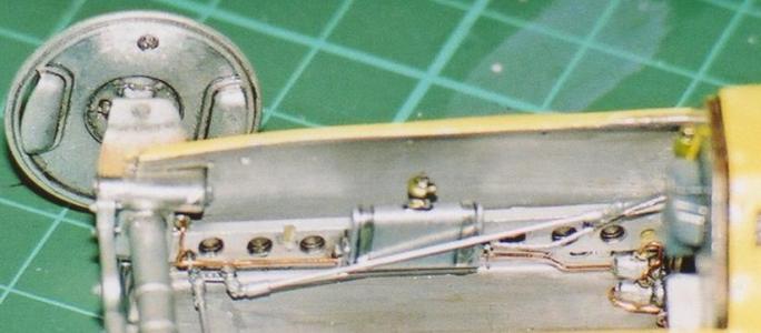
Brake lines and steering linkage have been fitted as the car starts to come together but the photo etch looms to hold the copper brake line to the chassis leg were sunk into drilled holes prior to painting. It is important to think about these points during the planning stages of your build.
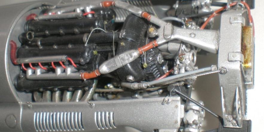
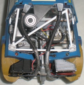
In this 1/20th scale Mercedes many details have been added. The carb’ unit went from a single moulding to a sub-assembly containing over 20 individual parts. Photo etch, wire and hex NBW’s were combined to make the linkages, pressure pitots as well as the fasteners and intake details. This is about studying the photo references you have, noting the shapes and adding them either from commercial sources or from scratch building, usually shaping and cutting Evergreen plastic rod and strip.
Careful painting of the moulded details really helps but sometimes you have to mould the details yourself. Weld seems were added to the radiator by using a thin roll of milliput pricked with the tip of a cocktail stick.
Once again a variety of fuse wire and plastic coated wire has been used to detail the engine, much of the drilling of holes has to be done early in the construction of the sub-assembly so planning ahead was again important. It can be helpful to make wiring diagrams to help remind you what is going were and to tick off later when you have done it.
Some times the piping and wiring is external. This 1/32nd scale Airfix de Dietrich conversion hasn’t got a full engine but all the visible detail was added using fuse wire, copper wire and finely wound guitar strings. An electrical resistor and aluminium tubing also feature. This demonstrates that simple odds and ends can add invaluable realism without costing you an arm and a leg.
In fact take some time to wander around your local craft shop and see what other crafts can offer. You will be surprised at the amount of useful things you can find, probably costing much less than from specialist car part suppliers.
Internet stores can provide a huge array of wiring and cable options from many manufacturers. Take the time to look at the pictures and check the measurements you need, your buying costs can mount up quickly.
Return to the Articles and Projects page.