SCRATCH BUILDING
It has been said that scratch building is just like making a kit, you just have to make the parts as you go along. Inevitably that takes longer but otherwise is essentially true.
On this page you will find information and advice on scratch building as well as a variety of useful examples.
Introduction.
For most modellers the idea of making a model from scratch is just too scary to contemplate. We know, it’s not that long ago we would have said “I could never do that”.
Although its not “easy” it is also not beyond most modellers. Once you have a grasp of the basic ideas the most notable requirement is the willingness to have a go, and to keep on having a go while you develop your skills. It is your choice how accurate you want to be, or how much detail you want to include. Our general advice would be remember this is a hobby and the main idea is to enjoy the challenge of the build and the pleasure of the result.
We started through doing conversions and making parts for detailing models, this grew little by little and as our skills and confidence grew we could take on bigger projects leading up to full on scratch building. It is probably a good idea to follow the same path.
Neither of us claim to be engineers or pattern makers, just ordinary modellers.
Before you start.
You will obviously need your usual modelling tools, certain supplies like plastic card in several thicknesses, evergreen strip and rod in a selection of sizes and widths, (half round, quarter round, ‘I’ and channel section). If you can get Model dr. or Grandt line hexagonal nut-bolt-washer sets these will be very useful, as will a selection of generic photo etch detail sets of which there are many available, don’t ignore military sets either. There are many useful tools to acquire that will make the process of scratch building easier. Equipment like dividers, a compass cutter, a small square, a Historex hexagonal punch and die set, scale rule, etc.... These tools do not have to cost a lot of money but usually the better quality you can afford the more accurate the results. Often the better quality items are easier to use too.
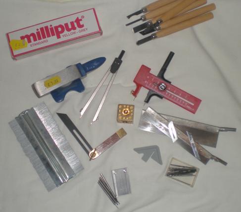
Here is a collection of tools built up over years of model making.
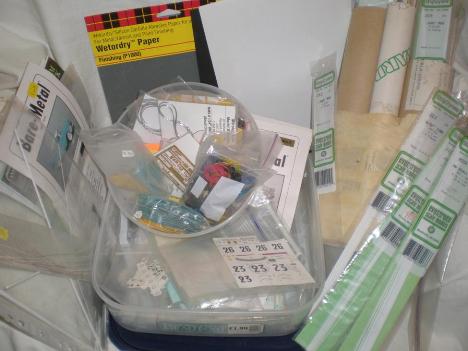
Below.
I keep my stock of odds and ends, rod and strip in a number of re-sealable tubs and old tubes.
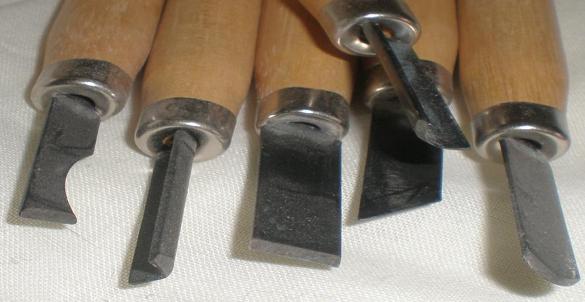
A selection of shaped chisels to help with carving soft wood or tooling resin masters. Shaped blades are also available for Exacto knives.

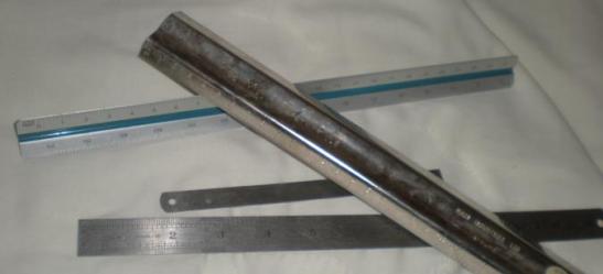
A scale rule is very useful this side shows 1/24th but several other scales are on the tri-star sided layout, including normal mm and inches.
A selection of steel rules is helpful for cutting plasticard. The 'M' shaped one helps keep your fingers away from the blade.
Guillotines and slide cutters are available for modellers too and these increase accuracy and safety no end.
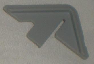
This centre finder is useful for finding the centre of wood or plastic rod, wheel inserts etc. You can make your own quite easily.
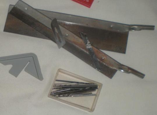
Avariety of saws saw blades and different size drill bits should be in most modellers tool kits any way but if you haven’t got any yet you will find them almost essential.
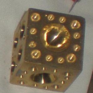
This dimpled cube has proved very useful over the years. It can be used for making dished lamp bowls, intake trumpet covers, lamp lenses and all manner of other items.
A punch and die set, or similar, does cost a lot of money but will pay for itself over the years. It allows you to safely and accurately punch out four different sizes of hexagonal nut or bolt head. There is also a version for punching discs too.
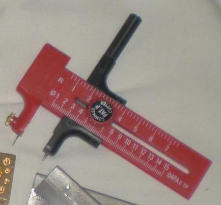
A compass cutter is a must but they take care and practice to get the best results.
They are not expensive and come with spare blades stowed within the tool.
Reference sources.
References can be found in many of the usual places, books, magazines, internet, etc. It is important to get as much information and as many photos as you can. Cross reference the photos and information as it isn’t unknown for photos to get the wrong caption put with them and all information is open to interpretation, even “Facts” can be distorted over time. Try to obtain contemporary publications if possible, you’ll be surprised what your local library can get hold of. You choose how far you want to go in researching your project.
A tip for your internet searches is not to just put in the car you are looking for. Try running searches for the designer, driver or race, or a particular event or even year. People don’t always record the car name next to the photo so you can find additional pictures recorded under other titles. It takes up time but is often worth it in the end. Remember to use your Favourites list as it can save you lots of time hunting for the ‘whats its name’ site you found the other day!
Colour photos can’t be trusted to give an accurate “colour” sample as so much depends on the camera, light conditions, developing chemicals and processes, printing ink brands, etc. In the UK Halfords have quite a useful reference book in their stores which can often give you the proper colour for road cars, and they can mix it for you too.
Remeber though, It's a hobby, so do as much or as little as pleases you.
Scale matters....
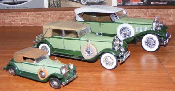
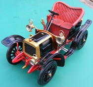
Three Packards in different scales, 1/43rd, 1/32nd & 1/24th. Showing what the difference is in practice. The most common scale for kits is 1/24th.
Back in the early years of car modelling it was 1/32nd.
On the European continent 1/43rd is preferred and it must be admitted that they do take up less display space.
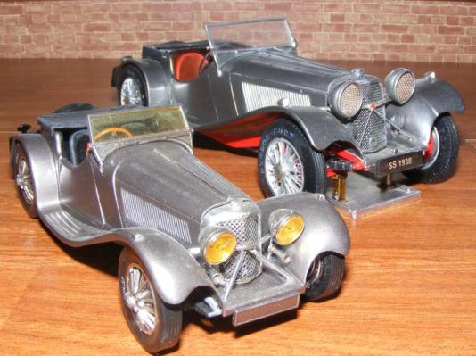
These SS100 Jaguars are in different scales, 1/32nd and 1/24th. A little clever positioning and careful photography and they are almost look the same.
Converting the scale of drawings.
If, like myself, you are interested in the vintage, veteran and Edwardian cars, of which there are few kits, scratch building becomes a necessary skill. However, drawings can be hard to come by and perhaps this is a reason people avoid scratch building or possibly it is because the drawings in an unsuitable scale and the thought of converting the scale puts people off the idea.
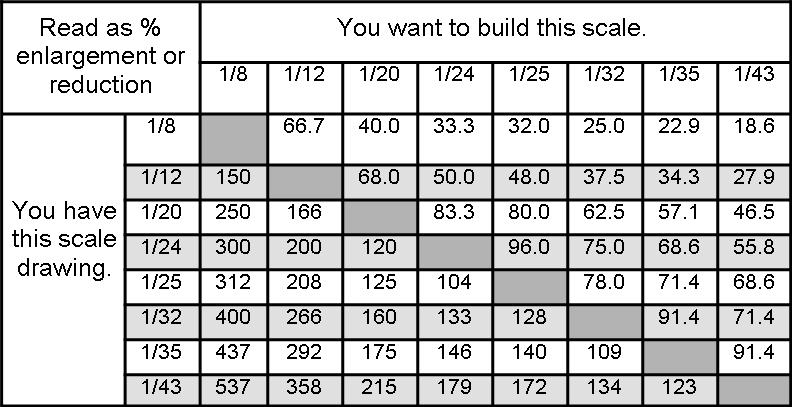
There is a simple formula to enlarge or reduce drawings: Divide the scale on the drawings you have by the scale you want to model and use the result to reduce or enlarge accordingly.
For example, if you want to build a 1/32 scale model but have 1/25 scale drawings,
divide the scale you have - by the scale you want:
25 divided by 32 = .78125. Now round down or up, as the case may be, and you have .78
Adjust the decimal point to 78, (you have to move the decimal because on photocopiers 1.0 = 100%, 1.5 = 150%, and so on) now set the photocopier to 78% and you will have your drawings in 1/32 scale.
To do the reverse and enlarge 1/32 drawings to 1/25 scale:
1/32 divided by 1/25 = 1.28; now round up, giving you 128% to enlarge the drawings by.
The chart below gives you popular car modelling scales and the enlargement or reduction percentages.
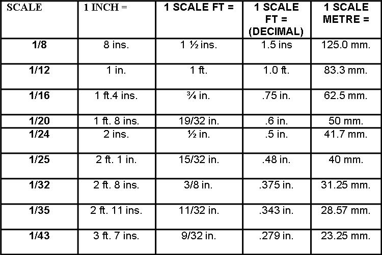
This second chart gives the popular model car scales with metric and imperial comparisons (just for information).
Popular model scales compared.
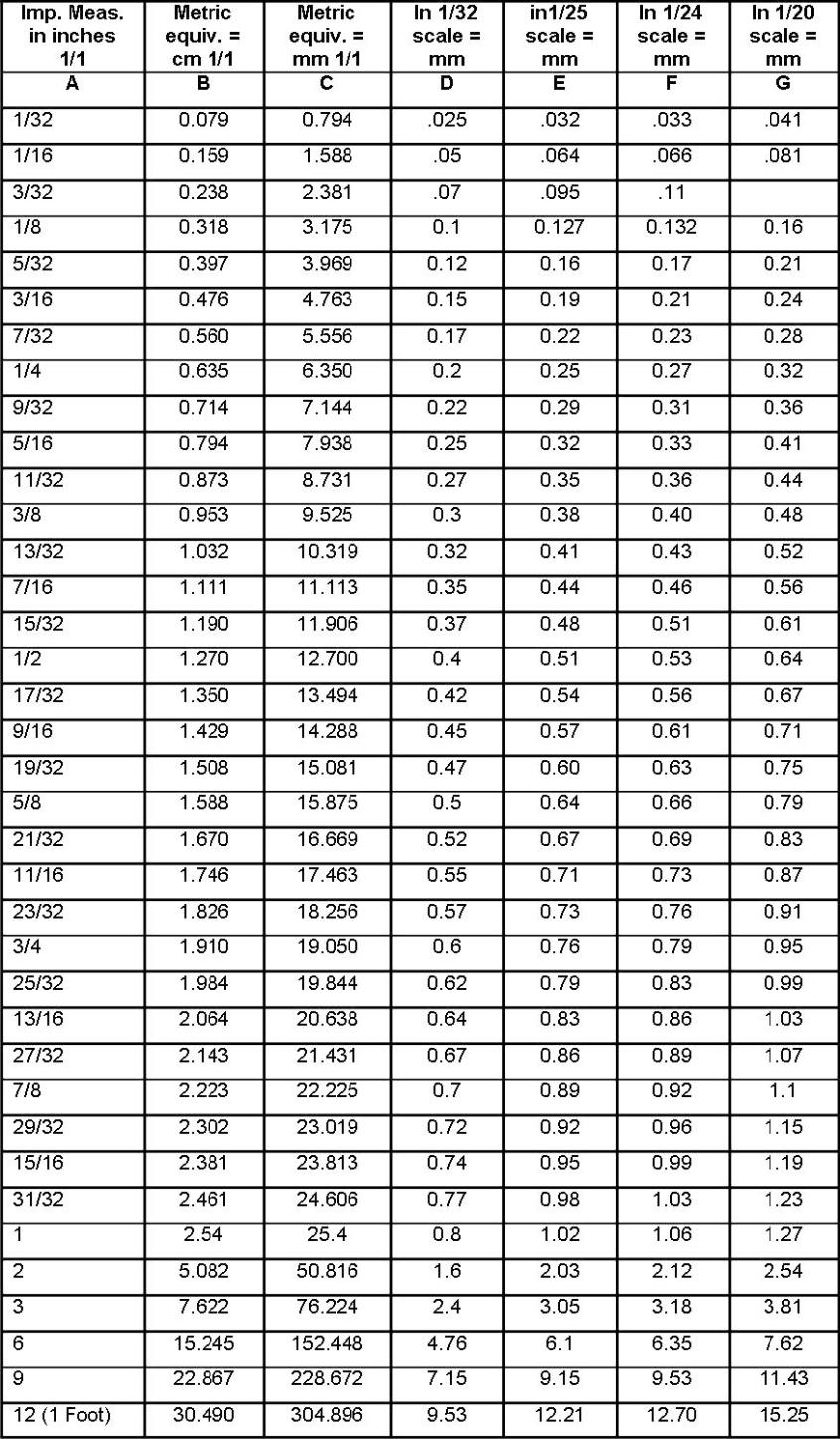
METRIC EQUIVALENTS for scratch building and conversions.
Column A is measurement of the actual 1/1 scale item.
Column B is the measurement in column A converted to metric centimeters.
Column C is the measurement in column A converted to metric millimeters.
Columns D, E, F & G represent the measurement required for each scale shown.
Example: Reading across, 1/1 size item of ½ “ would have to be 0.53mm for 1/24 scale model. Conversion: Part measuring 1.6mm on 1/32 scale model converts to 2.54mm for 1/25 model.
Drawings.
When it comes to making drawings what you really need is dimensions like wheel base, track, wheel and tyre sizes as from these you can produce drawings of the car you want to build. Overall height, length, width and ground clearance will be very helpful and the more dimensions you can get the better.
If you are doing your own drawings remember you want to be accurate but you're probably not going to sell them so don’t worry about your drawing skills, as long as you can work from them to your satisfaction that’s all that matters.

There are several sites on the internet where you can get plans and drawings for model making and they are adding to there listings regularly.
You may wish to become a member of some of these sites as it’s usually free and gives access to better quality images.
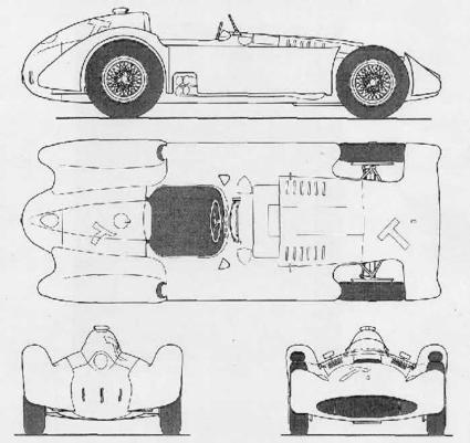
If there are plans available try to ensure you have top, side ,front and rear views. Be sure to check the plans against your information to ensure they are accurate. It is possible to develop the side and end view to create a top view if you know how. It is fairly straight forward to do by extending the dimension lines across the page to create the new view. This explains why so many drawings give the plans in a square grid formation.
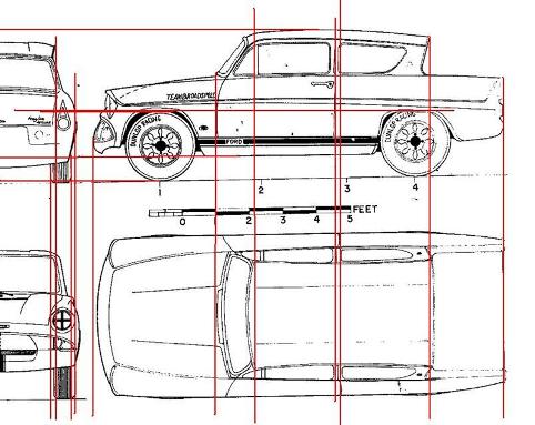
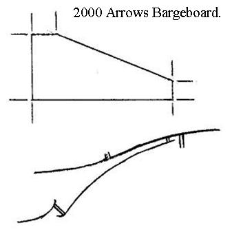
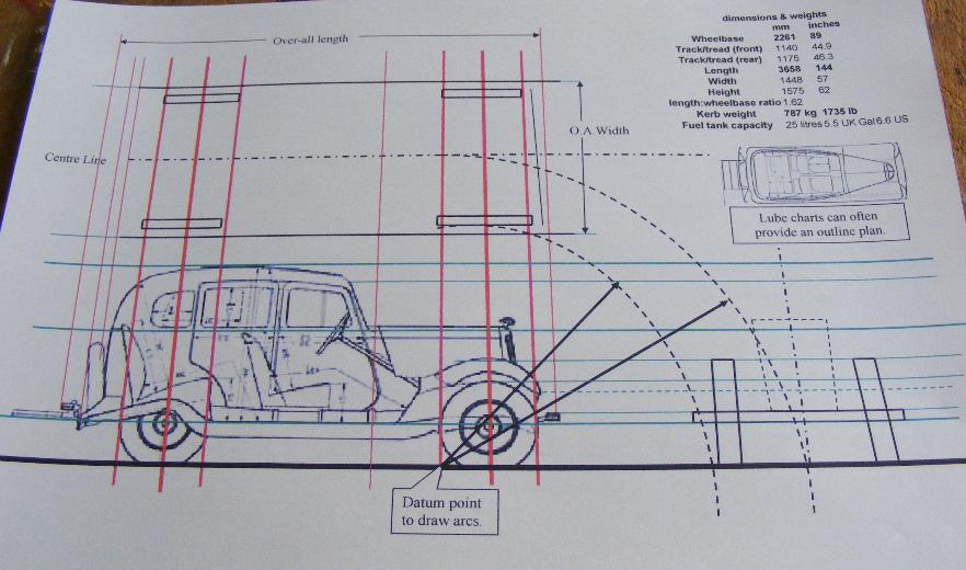
This drawing shows the basic principle of transferring information along the lines, using identifiable edges, joints or features. From these datum lines you can build up the other views.
Also visible on this drawing is how the plans drawn by others may not be perfect either, some of the lines don’t join up with the corresponding part on the other part of the drawing. This demonstrates why you should check things yourself. Check against photos, spec sheets for track and dimensions and against plans or even other models or toys in other scales.
If you have no front or rear you can transfer data using a compass as shown below. Drawing arcs will maintain a distance allowing you to note the important features. You must use the same 'Datum point' for all the distances though, that is most important.
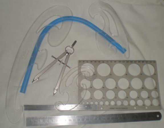
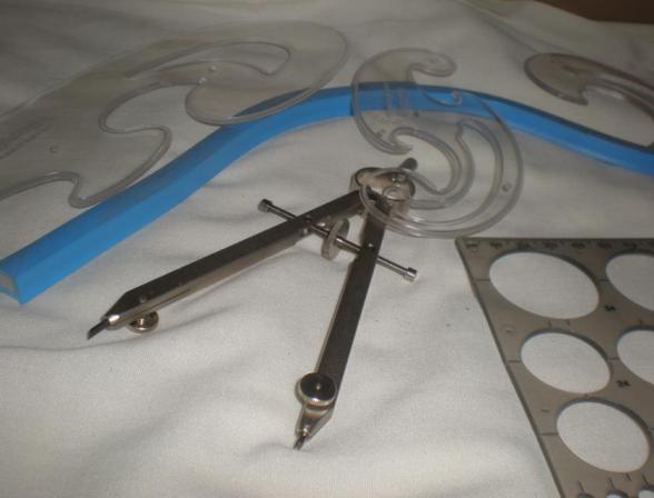
To help with drawing plans I have collected some useful drawing instruments together. A set of French curves, a good quality compass and set of dividers, circle template, a bendy plastic rule as well as my steel rules.
You can spend a lot of money if you choose, but try to think about the amount of time you will use these items and get value for money accordingly. No point buying the best of everything if you only intend to use them once in a while.
Chassis Building.
The manner in which you build a chassis depends very much upon the style of the chassis to be built. We will start with arguably the hardest form to build then move on through the other forms of chassis used by car manufacturers. Tubular space frames, box ladder frame or monocoque style we have made them all. The degree of accuracy and authenticity is, as always, up to you. You may be happy enough to use the first frame you make or you may take several attempts to reach the level you desire. Remember it’s a hobby and you’re supposed to enjoy yourself.
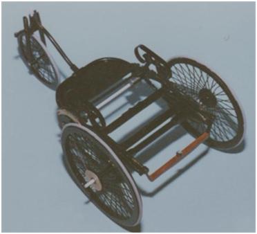
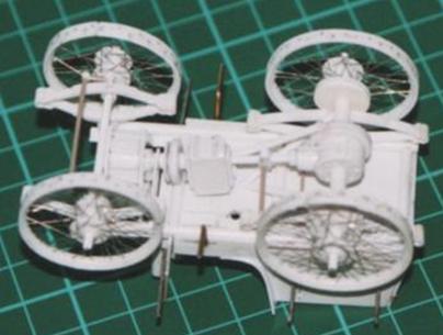
The real Benz prototype chassis was made from tube following bicycle manufacturing principles. Replicating this method means bending plastic tube as can be seen in the photos of the chassis, there is a considerable amount of shaping to be done. The most difficult of forms to replicate occurs were the tubing bends in differing planes. A quick study of the main chassis legs shows two angles on the horizontal front to rear axis but then another angle turning around the front of the chassis on the left to right axis. If you can find cored wire/cable of the correct diameter this is much easier to bend but much harder to work with, because it is so easy to bend. Keeping the straight parts straight then becomes the main problem.
Tube Chassis.
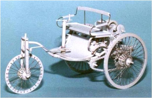
More information on the scratch building of the Benz Prototype can be found on our Articles and Projects page.
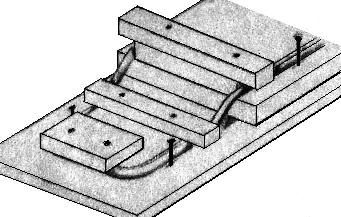
To bend strip, rod or tube successfully is time consuming, rush the job and you are almost certain to break the plastic and have to start again. A jar of hot water is required, but you must take all practical precautions to prevent scalding. The jar of hot water is needed because you dip the plastic rod or tube in, so it becomes softened, then you can shape it around the jar, or a knife handle or a jig you’ve made to the size you require.
Making a jig need not be hard as it sounds, one simple method is simply to pin a photocopy of the plan to firm surface then using the same panel pins mark out the curves you want. Obviously you need it to be strong enough to hold things in place while the plastic cools. If you prefer you can build up a plastic version using the plans to make a sort of photo negative that gives a trough to lay the tube inside. This can be as accurate as you like but is obviously more time consuming to build. The choice is yours.
You may need to hold the plastic in position for some time, use of simple things like elastic bands and pegs can do the job for you. You may need to repeat the process several times to get the shape you require, don’t be surprised when the plastic starts to straighten again as it cools, don’t forget to check regularly against the plans.
If you are having difficulty getting the plastic to hold the shape, after heating the plastic in the jar of hot water wrap it around the jar. The heat held in the glass will help the plastic mould to the new shape, you can use different sizes of jar to induce different sizes of curve. For tight curves use an elastic band to hold the plastic around a Exacto knife handle then let it sit in the hot water, the handle will absorb some heat, and just like the jar, helping the plastic take the new form.
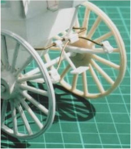
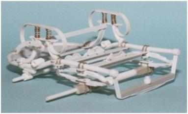
Another example of the use of bending for chassis’, this time wire, to form part of the elaborate rear springing system of the ‘Hansom’ cab.
Brass wire can be bent quite easily with pliers. For the top chassis extension cut a length roughly to that required make your first bend then place the wire on your plan to measure and mark the second bend. If you need tube to make brackets as on this model remember to slide them on before you do the second bend.
For the drooping spring shackle mounting you need to get the larger curve into the wire first, then mark and bend the more pronounced changes of angle into the shackles.
These warped parts for an Itala were taped to the flat sides of a glass bottle and hot water put in the bottle. The process of adding hot water and allowing it to cool was carried out several times until the parts became flat again.
Beware the glass can get very hot and burn skin.
The same process induces curves as well as removing them.
Shaping shallower angles in the fingers is obviously possible but often not precise. Try marking the start and finish of the bends angles before you start. Marking can be done with a pencil, CD pen, shallow knife scratch with dark paint rubbed in it, or even masking tape strips, whatever is most visible at the time.
Once the shape is coming close make sure you have the straight cross members ready, and any tube joints and strengthening parts too, all cut and measured against your plans and each other. “Evergreen” rod and tube is very good as they produce sizes specifically designed to slide in side one another, ideal for the braised bracing brackets in this sort of chassis.
Take your time to carefully glue the parts together, one at a time, paying attention to positioning and regularly checking all the angles against the plans. Remember to slide on any bracing tubes before you block their route with cross members as it is much easier to slide the tube along than to split it and try to fit over the rod or tube.
Choose your glue carefully. Some plastic welding adhesives evaporate and dry quickly, others more slowly giving you time to adjust the positioning of joints etc.
Ladder Chassis.
Next we will look at the traditional ladder and box style chassis used on cars for many years. Initially made from timber but later from stamped steel panelling and box section took over.
Study the picture of the Lanchester Forty chassis and you can see were the channel section strip has been cut and shaped, new strip added at the front and how a similar approach has been used at the rear.
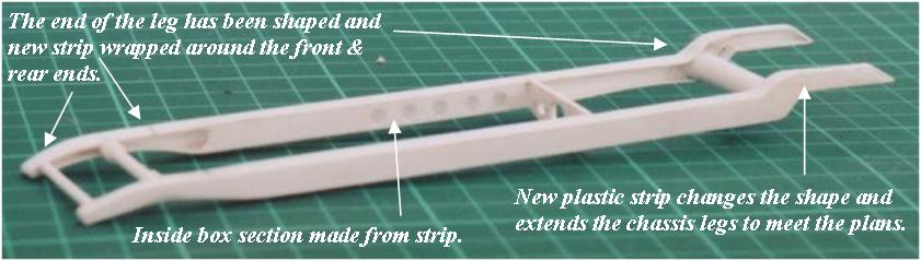
Although the chassis legs may have curved shapes in them they do tend to be straight. The job here is to replicate both sides the same. If you have strip of the right depth this will help immensely otherwise you need to cut two lengths of card to the same dimensions. If you need pressed steel channel section chassis legs again it helps to have the evergreen channel section strip to work from. Shape one side to match the plans first, don’t worry if you have to remove channel section top and bottom this will be replaced with plastic strip later. When one side is satisfactory use double sided tape to attach it to the other strip. This is the easiest way to transfer the same shape to the second chassis leg and means both can then be worked on together thus attaining the same shape for both chassis legs. If there is internal box facing to the chassis make these in the same way.
If you have had to remove any of the channel sides, and you probably have at the front and rear, reduce the leg size so you can fit strip flush to the channel side. Shape the strip to go around the end of the chassis leg, this is not easy as the strip breaks easily. Glue the strip in place on the flat only, fold it around into position then glue it in place at far end. If you get glue around the sharp fold at the front of the chassis leg it will break, sometimes into several small pieces that cannot be repaired. Fill in any gaps with fine filler and give it all plenty of time to dry.
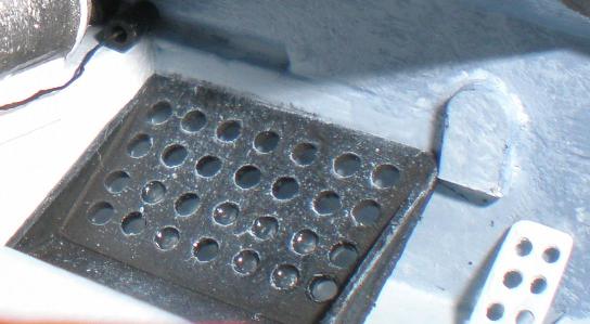
When drilling holes for spring shackles, or weight reducing holes, it helps to mark out a grid in the plastic to help maintain equidistant positioning.
Using a steel rule, and sharp knife, gently scribe the grid size you need. Rub some dark ink into the scribing to help you see it.
Start the drilling using a small size drill bit then increase the sizes of the drill bit over two or three steps to help build up the hole size but allowing for adjustments to be made.
This should enable you to keep the holes regularly positioned.
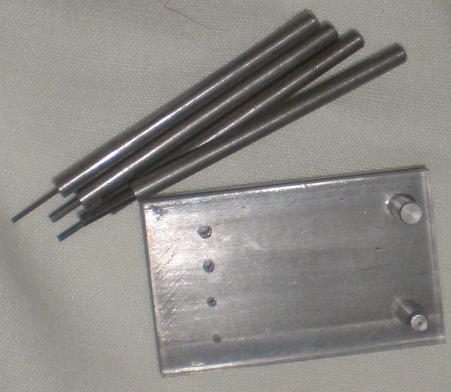
Before the pressed steel chassis arrived the chassis were made from wood, usually a solid beam carved to shape. This is easy for us to reproduce as we simply get two strips of evergreen that are the right dimensions and carve & sand them to shape. Use double sided tape to stick the two beams together and work them as a single unit, repeatedly checking against the plans.
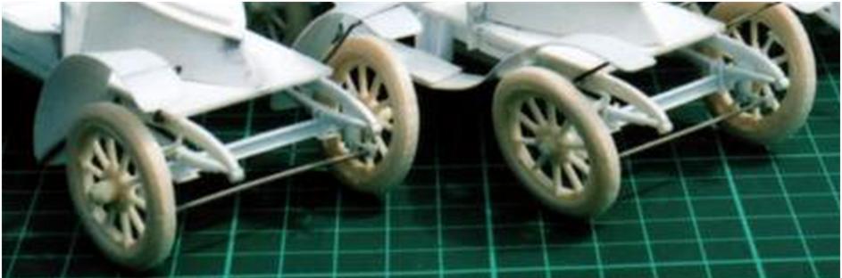
These two Vauxhall Chassis legs have simple beam chassis legs, cut & shaped from evergreen strip. They were made in similar fashion to those of ‘Genevieve’ below. The two pieces of rod go through holes drilled for the spring shackle mounts and provide a simple but effective way to hold the two legs together during the shaping process. This is much easier to separate than double sided tape too.

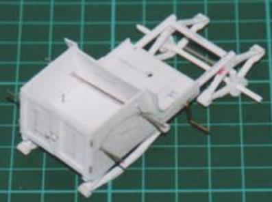
Chassis legs are usually mounted to the floor of the main body work so they can be properly spaced upon it and the cross members also secured to the underside of the floor adding strength.
After the chassis is done we can move onto the floor pan, that of the Lanchester forty is quite complex, but is constructed the same methods outlined already.
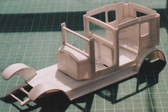
To paraphrase the great Gerald Wingrove just look for the shapes within the object you want to build, make all the shapes and then bring them together in the right order. It is pretty simply when you look at like that.
Make the flat base plate, make the side panels, make the rear floor and angled piece, make the running boards and the wings then bring it all together. That probably sounds very simplistic but provided you take the time to make sure the parts you make are the same for both sides you can make these complicated items too. One of the easiest ways to ensure wings are the same is mark both out a piece of plastic, score a dividing line between them, then bend the parts together, usually around a bottle full of hot water. Finally separate the parts and attach them to the inner wing former.
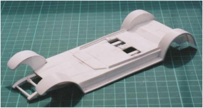
Body forming.
After the chassis and floor pan comes the body work. One way to approach this is endless carving and sanding from a block but for starting off it may be easier to start with a set of formers and lay skin over the formers.
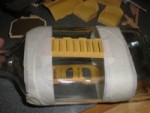
Here the bonnet of the 1904 Darraqc is built up over formers, a system also used for the Bugatti Brescia body in the Bugatti collection.
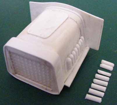

Raised areas on the body can be made by warming and shaping the plastic but it is often easier to make the shape from plastic card, strip or rod and add it to the body. You can hollow out the interior side if you need to but it isn’t always necessary .
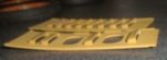
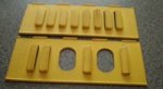
Louvers are a particularly common and annoying problem. Here the louvers for ‘Genevieve’ quarter round strip has been cut to length then the ends sanded and chamfered. You can go to great lengths undercutting and shaping the part to give a realistic appearance. You can go as far as you wish.
More complex body shapes are built up in sections, still from card, rod and strip. Paper templates can be helpful in obtaining the desired shape and are easier to trim with scissors before committing to plastic. You can see from these pictures how layering differing thicknesses of shaped card shapes can help build up the profiles required. This is then followed up with fillers and not a little sanding.
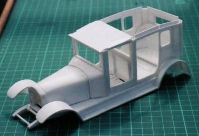

The sand colouring is the special filler primer rather than ordinary plastic primer. The processes of preparing the surface are just the same as for a normal kit. Little by little all the flaws are sanded out and finally an under coat of normal primer is applied. This is why the saloon body is grey, it is ready for its top coat of gloss grey.
More information on the scratch building of ‘Genevieve’ can be found on our Articles and Projects page.
More photos of the scratch built Lanchester ‘forty’ can be found in the luxury cars collection.
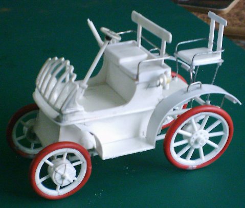
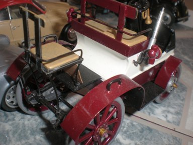
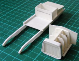
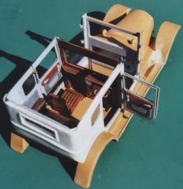
Some models require the combining of all the techniques. The Lohner Porsche has a tube chassis with a box body sitting upon it. From that are mounted the dash’, seats and wings.
Always keep your eyes open for items of use. The dash’ for this model was cut from a pop bottle which had the right compound curves in its neck, evergreen strip was applied for the strengthening.
In the same manner, electrical wire provided the tyres for the car and household fuse wire was used for the seat arms and supports.
Return to the Articles and Projects page.