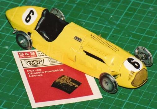
Detailing the Talbot-Lago T26c by Ian.
In this article we will take you through the building and detailing of this long serving French Grand Prix car. Using scratch building and a variety of commercially available parts to bring the model to life.
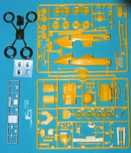
Heller’s T26c kit is very nice to work with. The detail is a little less crisp than modern kits by Tamiya but then it is considerably older. Compared to the Merit kit of the earlier model T26 it is far superior, as such it cries out to have extra attention lavished upon it.
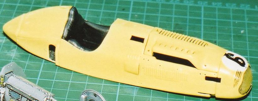
After all the sprue had been washed and dried construction began with the body. This went together well with just a little filler being needed to blend the seat parts together. All the seems were cleaned and sanded smooth.
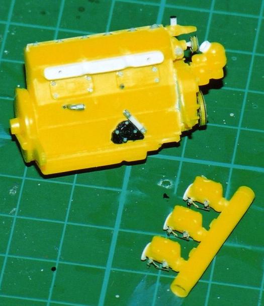
The basic engine block was put together and all the parts cleaned of flash or moulding defects.
I use small re-sealable bags to keep the parts grouped together.
One of the most important jobs in model making is planning ahead, and if you are going to do extensive detailing this becomes even more important. After initial body construction and preparation then the details get attention.
The body and bonnet were drilled to allow the fitting of fasteners & handles later in the build.
The pins for the bonnet clips were made by heating and stretching sprue, cutting it into smaller lengths, then heating one end by a match flame. This has the effect of mushrooming the end of the thinned sprue which recoils away from the heat.
Grandt line rivets can be used for this job if you have the right size available. This helps maintain regularity of size between the parts.
The ‘T’ handles came from a photo etched Wheel weight set by detail master.
By using evergreen strip, white metal hose and generic photo-etch sets it is possible to add the little details that lend reality to the model. Also visible here are the etched pulley faces used. Cored NBW’s for the spark plug leads and the small white tube added to the distributor on the front of the engine are drilled ready for the leads to be fitted later.
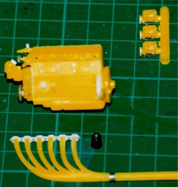
Both sides of the engine had p.e. details added to the cover plates, the pump face was detailed with small NBW’s as was the front visible side of the clutch housing.
The radiator was given additional detailing with plastic card, and evergreen strip. This gives some depth and definition. Using strip helps to maintain regularity of width and straight edges. Drilled white metal hose fittings were attached and a hole drilled at the bottom for the starter to go through to the engine, p.e. rings from the wizard of O’s range gave support to this area.
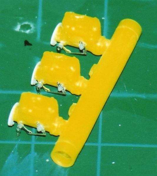
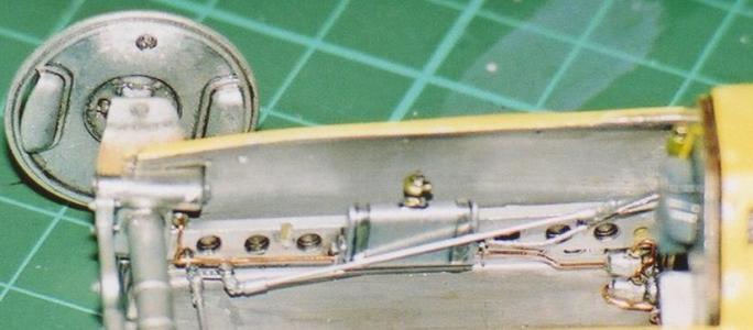
Neither the exhaust or intake sides of the engine had proper mounting plates. I made these from plastic strip and detailed them with small NBW heads, as can be seen on the exhaust and each carb’. The carb’s were also detailed with p.e. linkages (from detail master set) and connections made from fuse wire. NBW’s were also added to retain all the parts. I was fortunate to find several good reference photo’s to aid me in all this work.
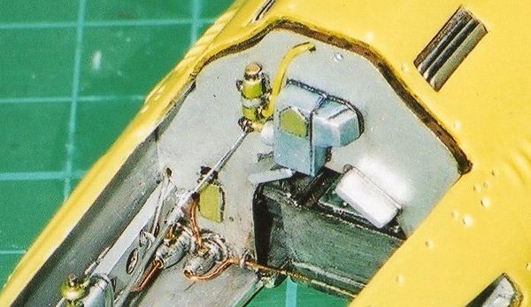
The firewall was detailed with brake cylinders and a steering box.
As can be seen converted parts from the bits box and p.e. sets prove very good at creating an illusion of reality.These were all drilled ready for the piping to be added after painting.
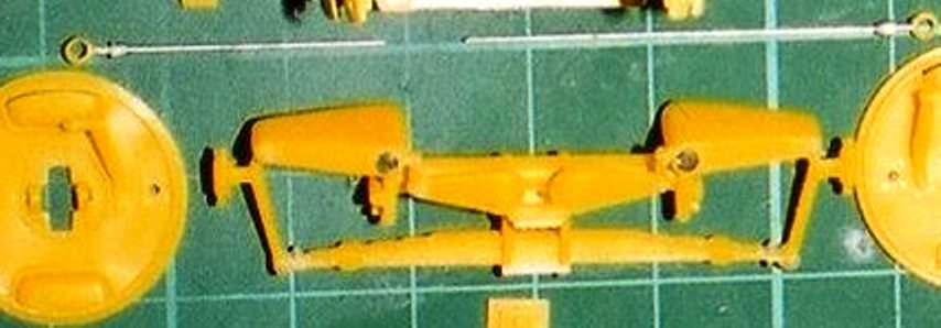
The chassis legs were drilled and S&S chassis loom parts super glued in place ready for the brake lines to be fed through them. The same p.e. parts were fitted on top of the legs with predrilled NBW’s added to replicate the links were the hard piping changes to the flexible pipe.
P.E. Hex and round shapes helped represent the front suspension rocking arms & NBW’s were used to detail the transverse spring shackles and linkages at each upright’s base.
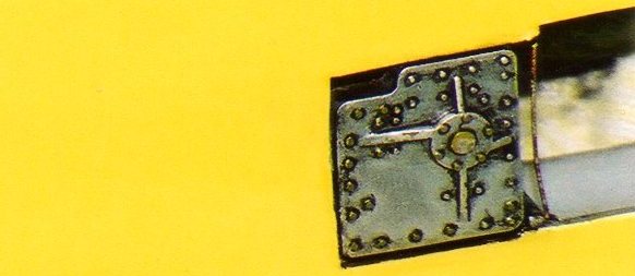
The oil tank behind the dash was fabricated from evergreen strip and card detailed with NBW’s.
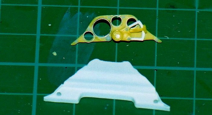
The Dash panel and per-selector gear shifter were then upgraded too. Firstly the dials were drilled out which allowed decals to be put behind the part giving depth to the gauges. Wizard of O’s rings were used for the gauge bezels. NBW’s & rivet’s were added for the mounting screws.
A new guard for the gear selector was made from plastic card. I made the outer shape then carefully cut & sanded out the inner shape.
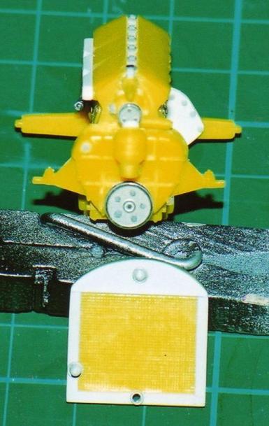
The moulded grill was removed using a hobby drill fitted with a grinding dental burr. The opening was tidied up with files and sandpapers. This was then recessed on the inside to allow the new grill to fit snugly up to the leading edge of the opening.
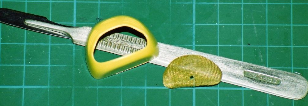
A new grill was made from brass mesh cut, over sized, around a paper template made by placing the paper on the opening and taking a rubbing of the edge.
The shaping was induced by using the end of the scalpel handled pushing down against a cutting mat. This took a while, repeatedly test fitting, but worked well in the end.
The worst problem was cutting the hole for the starter shaft. This was done with a small hole punch. A wizard of O’s p.e. ring tidied up the opening. The brass mesh had the added effect of not needing to be painted, I simply washed it with citadel inks to give it some wear and dirt.
Now for the wheels. The full process for this will be covered in our article on re-spoking wire wheels so this is just a quick photo' record to demonstrate the steps. Obviously one can't use the same plastic glue to secure wire to plastic, 'superglue' is the normal choice but it has to be used carefully.
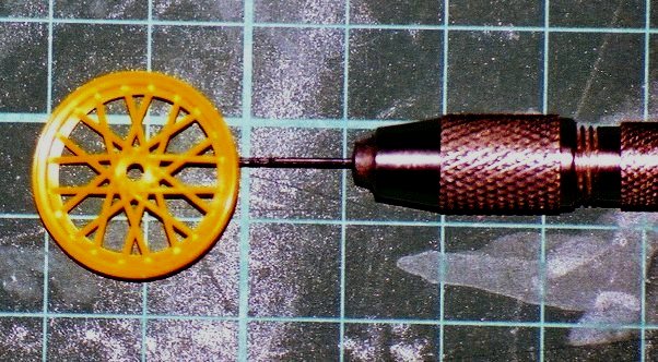
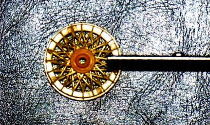
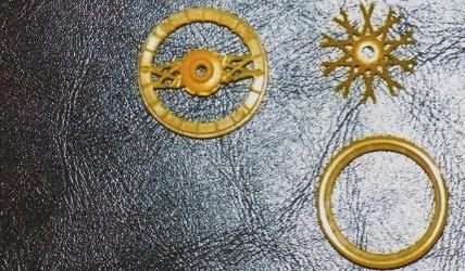
The process is a fairly straight forward one of marking where the spokes are, drilling or cutting the recesses for the new spokes, removing the plastic and fitting in the wire.
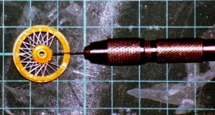
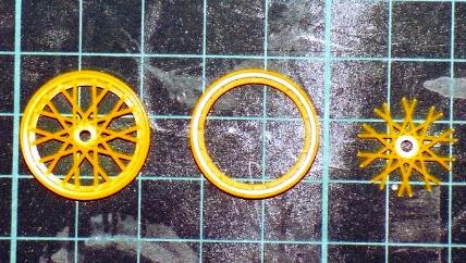
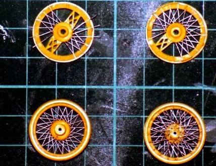
I worked on the front half of the wheel first as I didn't need to keep the centre, this would be glued to the rear half making a new hub. The rear half does need a different approach as the hub needs to be kept centered, easier than making a special jig.
Once the rear half is set the hub can be extended and the front rim be attached to the rear. If a few holes need re-drilling thats ok but ones has to take care.
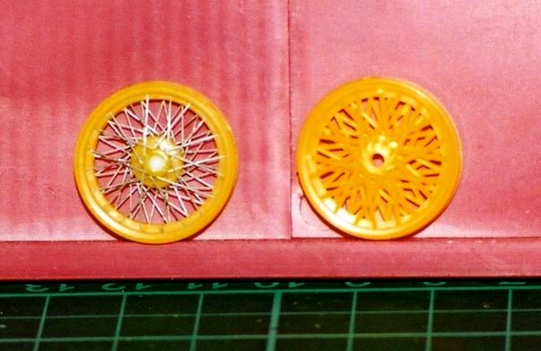
The last part is rebuilding the front half of the wheel spokes. To keep the pattern right it is advisable to do one weel at a time that way one can simply copy the kit part.
This sort of job does take time but as can be seen from the last photo' it makes a big difference. If you are worried about the strength of the wheel, don't be, they are surprisingly strong. Once painted they really look the part too.
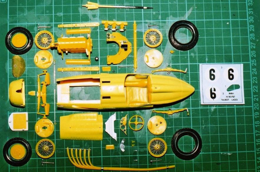
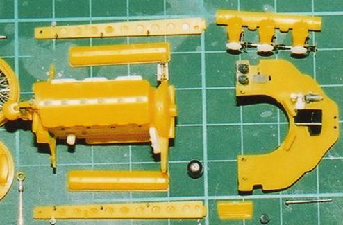
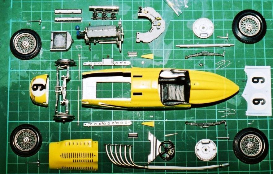
With all the construction of the sub-assemblies finished, detailed or scratchbuilt as required the parts laid out prior to painting.
The kit itself is nice so with the extra work put in all the potential is starting to show. A few of the parts are already mounted ready for spray painting.
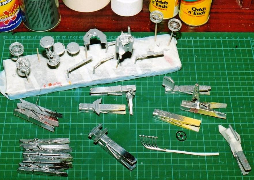
With all the detail building done we move on to the painting.
The starting point is of course giving all the parts a basic coat of colour. Here you can see several different methods to mount parts for painting.
Painting the parts is just as important in creating the illusion of reality as detailing the parts is. Subtle use of differing shades and washes of inks helps greatly as few things in life a truly one colour when we look at them.
The body colour was cut back with ‘T’ cut and the grill secured in place. Some test fitting of the body parts showed things looked good so far. The interior panel faces were painted with Citadel acrylic Mithril silver & washed over.
All the different added details on the fire wall get slightly different colour washes to pick them out as different from each other. with the addition of the final dark wash to put some shade into the hidden areas, these differences really do help.
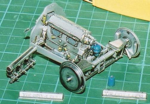
None of these parts have bees glued in place yet, this is just a trial dryrun. Each of the chassis legs, the engine and the front suspension unit need to fit together and be plumbed into each other, but they also need to be handled and fitted into the body piece by piece.
These pictures show how the use of differing shades of wash help pick out the details and emphasise them. Use of thinned 'Citadel' inks to “line” items gives a shadow were a join should be. This technique can also be used to give shade or dirt looks on larger surfaces too.
Bare metal foil was used with good effect on the intake tube which also had fine gauge mesh grills applied to the openings.
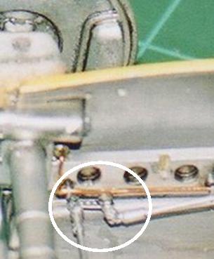
The copper wire was rolled on a flat surface under a steel rule to straighten it out. It could then be fed through the loom parts and on into the brake cylinders. Small dabs of super glue fixed them in position, although these days clear acrylic varnish is a safer option. Careful use of fine nosed tweezers helped to shape all the angles and turns in order to link up the hard copper brake lines to the flexible ones that lead on to the brake drums.
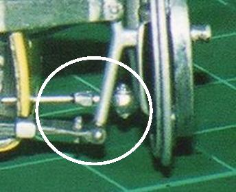
The steering linkages were made from fuse wire rolled out straight as described. The end linkages make use of the wiring loom parts with rubber tube representing the reinforced thicker part of the joint.
The links then get joined together by means of NBW’s.
The track rods have white metal hex hose ends drilled and used to detail the link to the steering arms.
As can be seen on the left.
Picking out the detail on the bottom of the gear box by means of ink washes and dry-brushed highlights.
The bottom of the car can be 'dirtied up' later using the ink washes as stains.
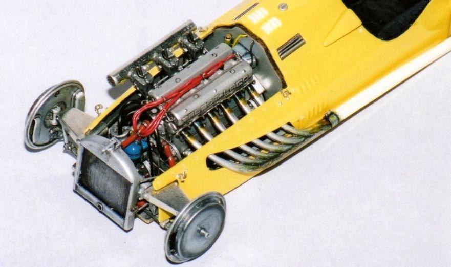
The picture shows the completed engine bay. Brown hoses feed to the radiator hose clips are made from silver Trimline strip. BMF can do the job too. Red plug wires are secured by super glue with fuse wire clips to keep the cables tidy.
To obtain the required look for the exhaust pipe it was painted with white primer, then masked and the header sprayed metallic silver-grey. The heat staining was done by use of citadels ink colours washed on over several hours.
Heat staining throws up some colours and combinations of colours that could not be guessed. Everything from orange to purple can occur, sometimes even green pops up. Take some time to observe these effects and practice the effects using brushes and airbrush. You will find differing inks and application techniques give differing results.
The use of ink washes can also be seen to pick out the lettering on the rocker covers, and on the face and filler cap areas of the radiator.
With the oil tank in place the cockpit is taking shape, it was washed wit inks too.
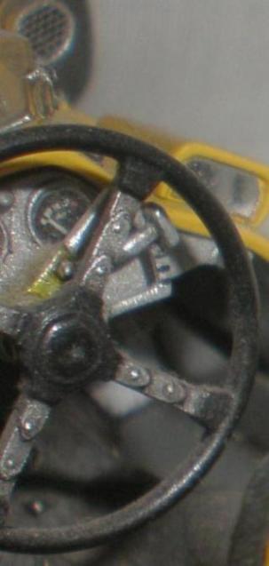
The steering wheel and dash all painted and washed with inks. Dry brushing with lighter colours helps pick out the details.
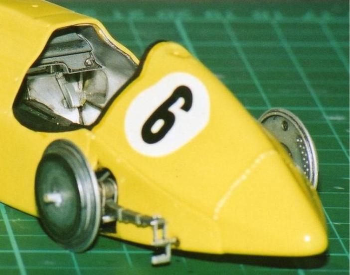
Same techniques were used on the brake drum covers to pick out details and to simulate heat staining.
The fine mesh grill on the air intake pipe can also seen in this picture.
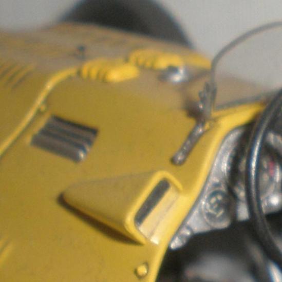
Photo etched brackets from an S&S set were used for the windshield supports, small NBW’s help hold it all together. The frame of the clear kit part is covered with BMF rather than painted.
The mirrors are augmented with a product called “mirror glass”, it comes on a sheet which needs to be cut to shape. Not easy to handle but very effective. You can achieve a similar result by planishing the metal foil of a take-away food carton.
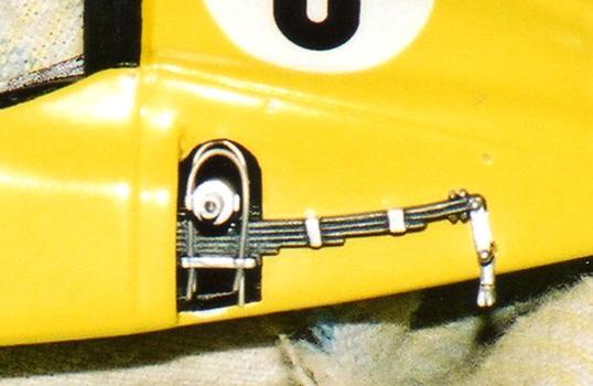
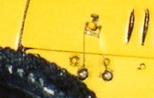
In this photo the rear spring details can be seen. NBW’s were used to detail the spring shackles. The use of blue and black washes to pick out detail in the spring leaves is also evident.
The Axel shackles were made from Evergreen strip cut shaped and drilled to give the base plate. Once the silver paint was dry silver-grey wire was threaded through the holes over the axel and secured with superglue before the excess was trimmed off.
Bonnet catches were fabricated from 4hole p.e. S&S wire loom parts carefully drilled out to fit over the bonnet peg catches. Each one had to be formed using thin nosed tweezers.
They are threaded with thin wire secured in the previously drilled holes by Grandt line rivets which were then painted silver.
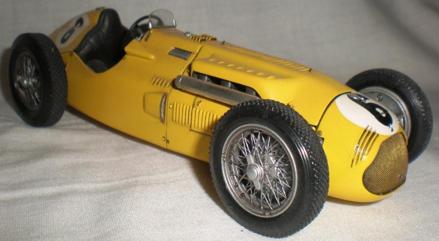
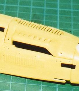
All done and dusted, the louvers were picked out with some ink and the final tiny grill of fine mesh added to the air scoop, along with a reinforcing strip of silver trimline.
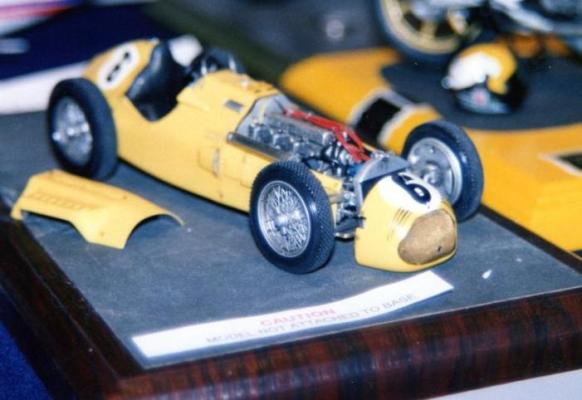
1950 Monaco GP car of J. Cleas racing in his national colours and finishing 7th.
Apologies for the photo quality. This car was built in the Mid 1990s and the photographs are scanned from the original photos and are not of Digital quality.
For more pictures of this and other Talbot-Lago Grand Prix cars,
GO TO -
