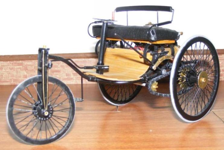
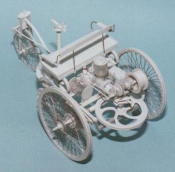
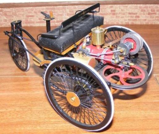
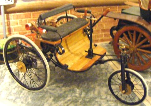
Benz Prototype, scratch build.
To help you build on the knowledge you have already gained from the pages on scratch building, and so you can see the practical applications, we will take you through the building of the Benz prototype.
The obvious place to start with any scratch building project is with the research. The better prepared you are at the beginning of the project the easier it will be. (If you haven’t read our foundation pages on scratch building then it might be an idea to do so now.)
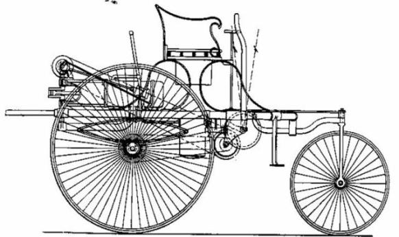
There is plenty of reference material for this car, in the form of drawings and photo’s, but little information regarding dimensions. Rod created his own drawings scaled from the one definite dimension he had - the bore of the cylinder.
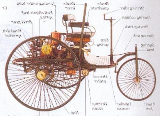
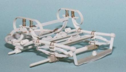
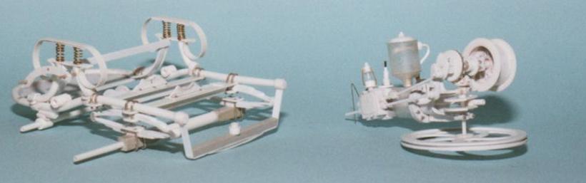
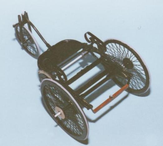
With this model, as with most vintage/veteran cars, the starting point is the chassis. This is a simple looking frame owing much of it’s character to bicycle design and fabrication ideology. However looks can be deceiving.
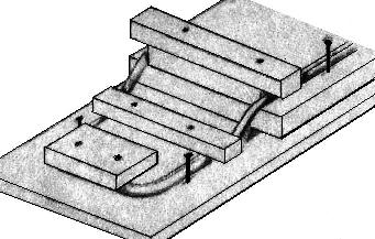
A jig was made from off cuts of wood and panel pins. It was kept as simple as possible to facilitate the repeated placing and re-placing of the plastic rod.
Plastic rod could then be warmed and left in the jig to cool, this operation is repeated several times in order to coax the rod into shape, little by little.
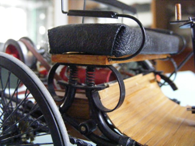
This process of warming the plastic and bending it recurs in the shaping of the seat mounts.
Once the basic shape is obtained the cross members could be made and attached. A sheet plastic floor was also put in the front of the frame to strengthen it further, this would later be hidden under the slatted wooden flooring.
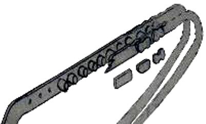
The methods for attaching the leaf springs is evident in the photos, as is the fact that each part is made from scratch. The seat springs are made by wrapping copper wire around a cocktail stick. The leaf springs are made from lengths of Evergreen plastic strip and rod.
The road springs are of the ‘full elliptical’ pattern, that is they consist of two sets of springs making a circular arc with the springs linked at their tips. The springs are made from lengths of plastic strip to represent the leaves, drilled centrally and fastened onto a rod post. From this the leaves can be shaped and glued together. more information on how to make leaf springs can be found in our article on scratch building Genevieve the 1904 Darracq.
When building from scratch it is especially important to measure and test fit all the parts to ensure you stay within the plans and that all sections and parts line up properly. There is no substitute for patience.
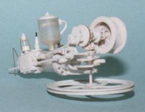
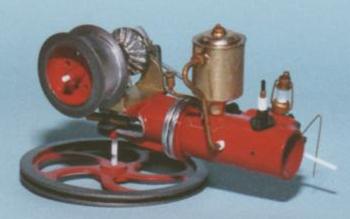
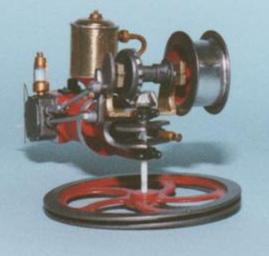
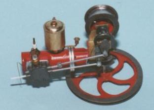
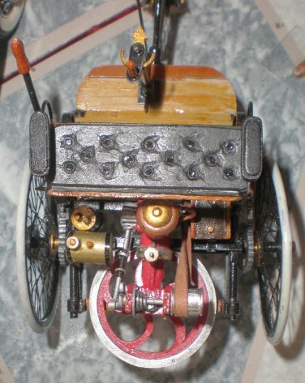
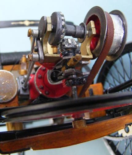
The engine looks more complicated than it is consisting mostly of rod and tube. As can be seen in the photos use of other materials should not be excluded, medical syringes made perfect replica fuel and water tanks.
The guiding principle is to study the item you wish to replicate, look for the shapes within it and then build up the shapes from the inside out. Most of it is not that hard once you start and gain a little experience and confidence.
Make use of proprietary products to ease your build. Here ‘Model Doctor’ nuts and bolts have been used to detail the engine. These days there are many photo etched sets of nuts, bolts, screw heads and fixings as well as ‘Model Doctor’ and ‘Grandt line’ plastic sets.
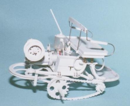
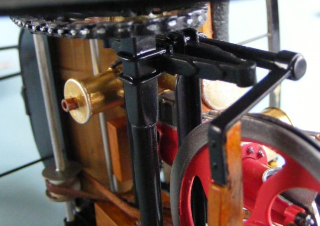
If you are thinking the advice given sounds a bit simplistic well take some time to really look at these engine pictures. Look for the tubes, circles, rings and boxes. They are all present.
The main cylinder is one length of tube, but by putting two disc rings around the middle (and adding a few nuts and bolts) it starts to look like to tubes joined at the flanges.
Hopefully you can now see what we mean by finding the simplest shape then building the details over the simple shape. Little by little it builds up as detail after detail is added.
The principle extends to all the areas of the build. Chassis, engine, seats, fuel tanks, whatever......
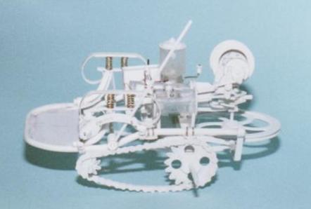
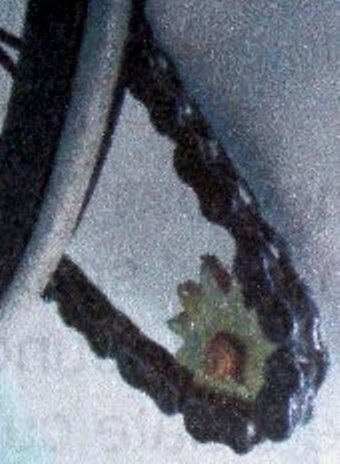
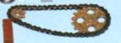
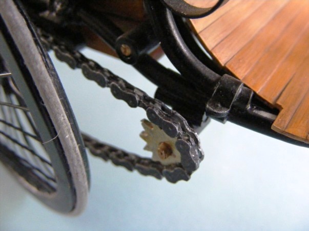
The sprockets for the drive system were made using simple school geometry and drawing skills. The main thing is to take ones time in marking out and preparing before cutting. It’s easier to take a little more off than to try and put it back! Having fixed the positions of the power and drive shafts the distance between them can be measured and the chains made.
As for the chains, well in 1/16th scale these could be made of individual links just like the real thing. This is a time consuming process of cutting ‘Evergreen’ strip into the same size lengths and then sanding each one to shape. In order to simplify this process the inner rows of the chain links can be cut in two rings from a flat plastic sheet of the same thickness as the strip. This gives the advantage of shaping the droop of the chain while adding strength to the assembly. The individual links made from strip are added to the outside of the ‘rings’ which are then shaped to represent the inside links, more time consuming than difficult.
The rollers can be cut from rod but are easier to make if you can punch them from strip or sheet using a Historex round punch and die set.
Once painted, this system of recreating chains is highly effective.
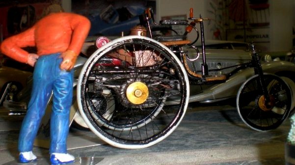
The method of constructing wire wheels is covered in our article on re-spoking wire wheels so we won’t take up space explaining it here. Simple electrical wire was used to form the tyres.
Once all the parts are made the painting stage is much like any other model. Because of the era of this car there is quite a lot of bare metal too (see the painting section of the ‘How to build a model car’ article) on this occasion Bare metal foil and Tamiya clear orange have been used for the brass parts. Halfords acrylic car paints were used for the chassis and engine colours.
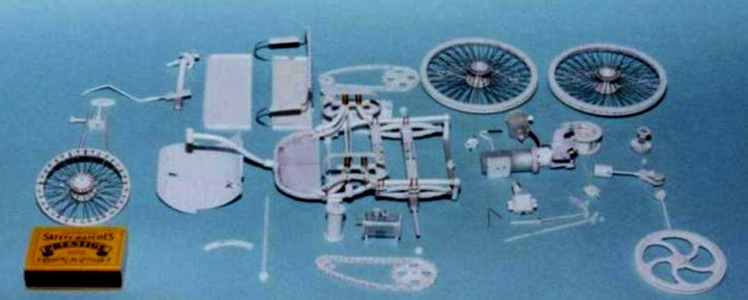
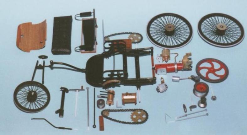
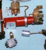
As can be seen from the break down photo’s each individual part has locator pins and holes built in just like any injection moulded kit.
Scratch building has been described as being the same as building a kit, you just have to make the parts as you go along.
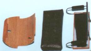
The wooden flooring is replicated from a single sheet of plasticard. Individual ‘planks’ being hard to maintain control of. The technique is to mate out the shape then mark out the planks. Using a scribing tool to deepen the gaps between planks and then some coarse sand or glass paper drawn across the surface, in the line of the planks, to introduce some graining. Once this is done the part can be cut out and shaped to fit.
The seat covering was made from leatherette cloth sewn down and plastic disc buttons glued in place.
The linkages on the valve cams are all made from evergreen rod and tube. A good quality set of drill bits is very useful in scratch building, as is the Everygreen rods and tubes that fit nicely inside one another.
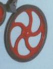
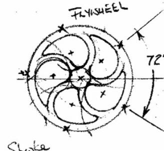
In order to make the toothed gears which mesh with the fly wheel and valve cams plastic strip was glued to a syringe nozzle which just happened to be a prefect angle for the job.

The front wheel forks are a simple construction using rod supported by a strip cross member and oval shaped capping. A rod pin through the steering head secures the fork to the frame.
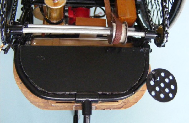
The steering gear itself is more complicated. There are three component units.
-The outer steering column with the quadrant at the top and guide box at the bottom.
-An internal shaft with the steering lever at the top and operating pin at the bottom.
-The steering rod and arm that connect to the front wheel forks.
The pin at the bottom of the internal shaft operates through a slot in the square guide box into a hole in the steering rod. As the steering is turned the pin slides through the guide and actuates the steering rod and arm.
This complicated structure has a limited turning circle.......but so did the original ca!r
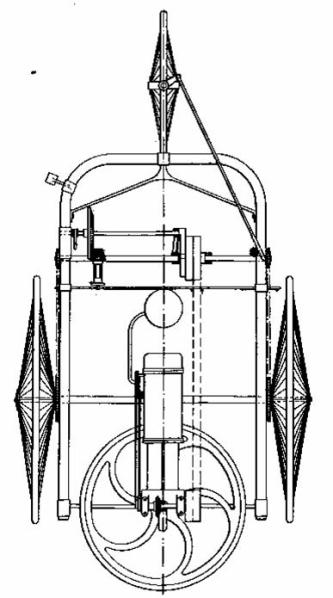
The drive from the engine drive wheel to the gears was by belt. A common place idea in water mills and agricultural steam engines at the time.
Being more flexible belts can be turn the power through 90 degrees as well as being transferable between different size gear wheels and tensioned by spring loaded wheels. On Rods models scrapped down leather was used for these straps.
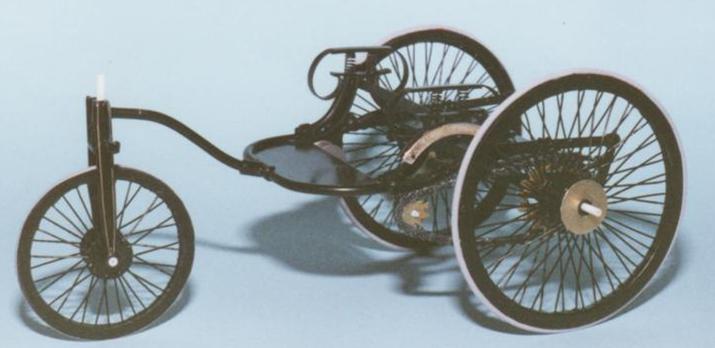
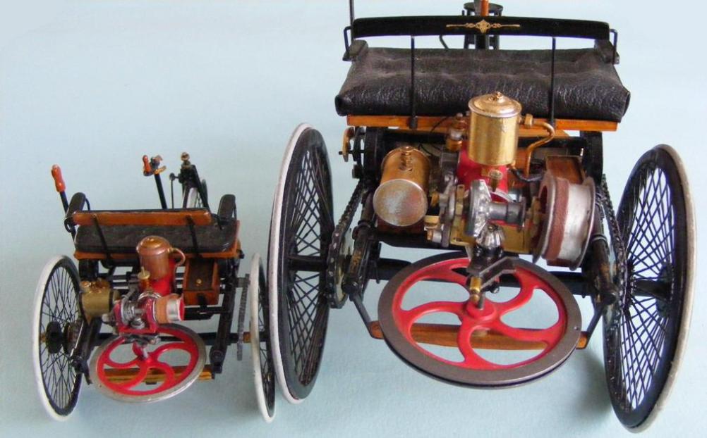
The end result is a highly accurate model of one of the worlds most defining moments in engineering. Without this, and Daimlers motor carriage, the world be a very different place today.
This page is still under construction,
We are sorry for any disappointment,
Please come back soon and see the progress.
OR
If you have a question please feel free to e-mail us at,