Restoring the BRM P261
by Ian.
It never fails to amaze me how generous modellers can be to each other. Over the years of attending models shows I have been lucky enough to meet some really nice people and we all help each other out whenever we can. But every now and then even I get a surprise.
I was given this model after a conversation at the Potteries model show 2009 and am ever so grateful for it. The kit is by Cox from the U.S.A. better known for their slot car products and this kit shows simplifications and strengthening that would have made it easy to motorize. It may have been a simple spin off from their slot car range but either way it is so rare that I couldn’t even find it on the internet. If there was a range of these static kits it eludes me still.
If you have a spare $1000 you can pick up the original mint condition slot car version though.
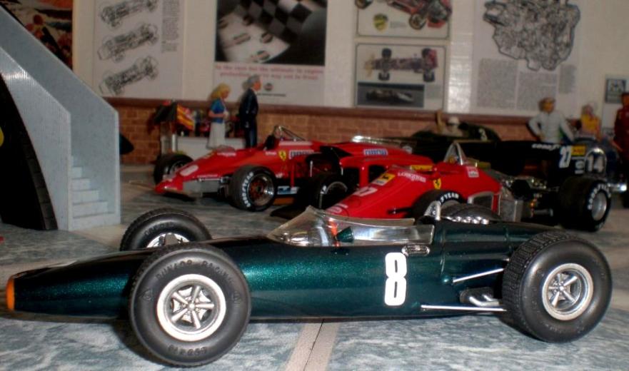
I am a Graham Hill fan so I had to make this car with the Monaco ’64 numbers. I had several photos of the car during the race but mostly black and white and from distance.
The kit has very bulky front suspension, simplified cockpit and the rear suspension has no engine or gearbox to hang off. All this is probably due to the need to fit a motor in and take the rigors of slot car racing; also we are talking of a kit from the 1960’s.
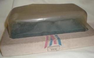
The model had been on top of a wardrobe since the ‘60’s and its presentation case bears witness to this, however the model inside had fared well and although it seemed to have a couple of parts missing it wasn’t anything that could not be easily replaced.
I mused for some time on how to upgrade the model without spoiling the character of the kit. Eventually I realised I would have to compromise on details and accuracy. I resolved to use as much of the original kit as possible while making additional parts to improve the model and bring it more up to date as a model.
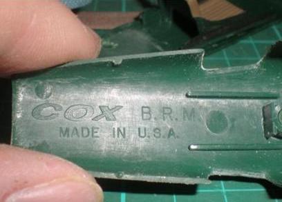
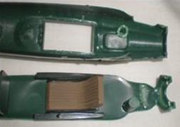
It seems obvious but first we have to break the model down. This in itself brought some surprises. Initially I thought the heavy mould lines down the sides of the body were joins but the bottom of the body comes out so the side moulding lines were just that. It took quite some time to remove them. Once I had got the two body parts separated I was excited to see the COX logo inside the nose, it almost seemed a shame to have to cover it up again. I noticed that the body sides were rather flat and the profile isn’t as round as it should be. The rear view mirrors are mounted on the body but should be on the screen (some filling would be needed). I could not do much about the exhausts, which are simply stuck on the body, and as I mentioned I wanted to keep some of the character of the kit. So I levered them off and cleaned them up for later use. As I said before it’s an old kit. I wanted to save the BRM logo decal if I could and spent an evening soaking it in microsol to try and lift it. This technique has worked in the past, but not this time. It isn’t a disaster as the colours are wrong anyway but it was another little step away from that character I was trying to maintain.

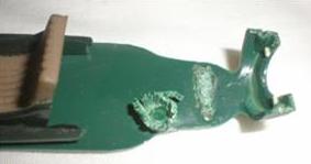
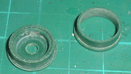
The rear suspension was well glued in and broke as I removed it. It was easy to fix though. While taking the wheels off I found the tyres were in two parts with a side wall fitting into the tyre. The wheels fit both sides and lock the tyres together. This is important as the nylon the tyres are made of does not take any normal styrene glues. The seat was securely attached to the body bottom and I could not persuade them to part company. Clearly I was going to have to do the cockpit and then mask it off aircraft building style. Fortunately the windscreen had already come loose and was in good state of repair, possibly a little yellow. There were some very heavy mounting lumps that joined the bottom to the body and these had to be removed as they were in the way of the new gear box and front mounting bulk heads. I used side cutters to carefully remove these lumps.
Once all the parts were separated and cleaned up I put them in plastic cartons for safe keeping. The chrome parts all went in together to be stripped off with oven cleaner. The chrome was heavy but the real problem was the heavy mould lines. I had to clean up the mould lines and that would ruin the chrome anyway. Also many of the parts just weren’t as “chrome” as all that.

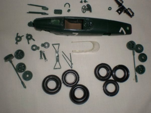
Over all, as mentioned, it is a solid, lumpy kit. The potential however was very evident.
I checked the model against some plans and the overall dimensions were pretty good. After studying the photos for some time I started planning the rebuild. How much could I update the kit without destroying its unique character? A list started to emerge. It seemed readily apparent that a gear box would be needed to fill the void in the rear body, this whole area could take some more detail and new parts would be added to the rear suspension (springs, shocks, antiroll links etc.). The cockpit could benefit from some wiring and foot pedal details and new fuel tank sides, front and rear fire walls. The front suspension was to be replaced entirely and would need to have some detail in the front suspension bays added.
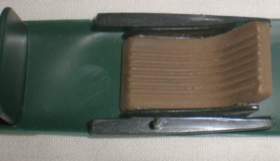
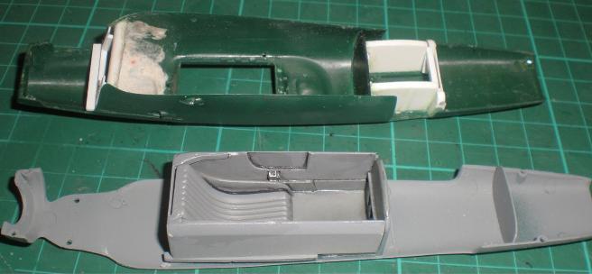
A new cockpit......
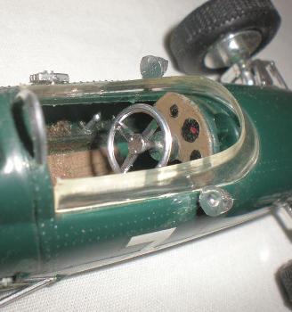
The fuel tank side panels were cut from some thick plastic card. This would allow me scope for shaping the area around the gear lever. Slowly scribing away the plastic as needed and smoothing with chisel edge Exacto blade was the technique employed. The sides were cut to sit on top of the plates on the kit seat part. Photos seem to give the cockpit a cramped look which was not evident from the kit parts. I made the gear shifter housing in two parts. The block was shaped from some stock rod then a top plate was made from thin strip. I drilled out the ends of the slots of the gear shift then cut out the area in between with a sharp scalpel. Once glued in place, and the glue dried, I drilled out the centre ready for the lever to be added later. Finally I could glue the housing in place above the spot of the old gear lever. Some simple pedal detail was set against the front fire wall. Simply made from plastic strip these are not easily seen but will give the illusion of reality should anyone look deeply into the cockpit. I made a new fire wall behind the seat and added some shaping to the top of the rear tub with plastic strip and blocks. This was then filled and sanded till it gave the look in my photo references. Thin strips of rod and card helped to fill in the open spaces so the cockpit would look more “tub” like and realistic. Finally I smoothed down the dashboard area and drilled some holes ready for cables and wiring to be added to the cockpit later. I considered opening out the cockpit top area in front of the dash as it should be on the real car. However I decided not to in order to maintain some of the character of the kit. I satisfied myself with a new filler tube and cap for the fuel system.
It was at this point that I decided to attend to the windscreen. I carefully measured and drilled new holes to mount the rear view mirrors on it. My photo references showed a small clear addition to the windscreen and I replicated it from thin clear plastic from some old packaging. This was attached with clear gloss varnish.
After that I carefully marked and drilled the hole for the filler cap. the hard part was thining the edge down so the windscreen part didn't look too unrealistically thick
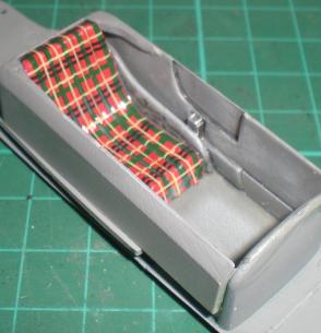
Knowing I was going to have to paint the cockpit before the body I sprayed the cockpit area with Halfords grey primer, then washed this a few times with citadel armour wash ink. This helped bring it to life a little. After some dry brushing with light grey it looked a lot more lifelike. Some clear satin protect sealed the primer and gave a sheen that looked like the photos. Once it was dry I painted the seat with several thin coats of citadel red acrylic paint. I then added decals raided from my spares box to give it the plaid. It isn’t totally accurate but gives a good impression of reality. The decals were applied in several sessions so each layer could dry before the next went on. This avoided them moving around while trying to position others on top. When they were all on and dry the seat was washed with ink and sealed with a coat of clear matt varnish. I have seen several photos of BRMs with this seat colouring and made some 1/43rd scale models with decals in similar colours for the seats. Either way it helps break up the dark green colour scheme.
Incidentally Raymond Mays said the only reason BRM changed from the light green colour to the nearly black colour was because the team found the light green paint so hard to keep clean.
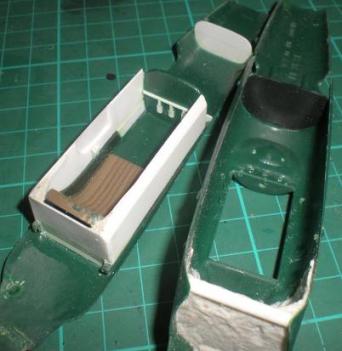
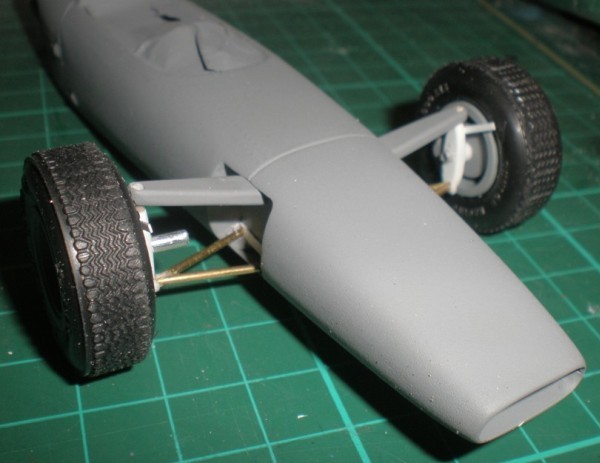
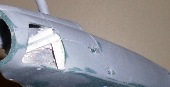
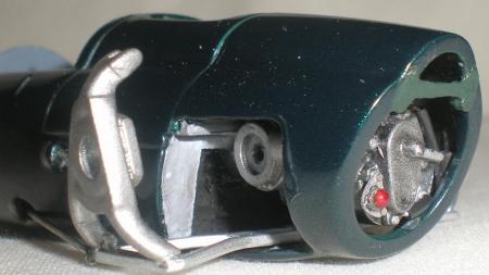
With the cockpit painted up I could put the body parts back together again. After several test fittings it was clear I needed to support the rear of the body so I added a tube brace at the rear then covered it with doped tissue. Later I would build a proper bulk head to this matching the ends of the extensions from the main monocoque tub. The front end of the body needed support and something to mount the front suspension to. I built in some bulkheads using the ribs inside the nose for guidance. A blanking plate was also put in at about the level that the radiator should have been. After lots of dry runs I had everything fitting nicely. It took rather a lot of filling and sanding before the body joints were all smoothed out. Some of the filler was Isopon 38 while superglue was used in other areas to give strength as well. Masking the cockpit with paper and masking tape trimmed to fit I was free to start spraying. Several coats of primer sanded down in between and I had a basecoat ready for the main colour coat.
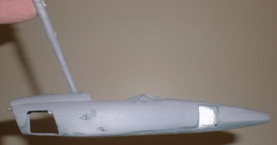
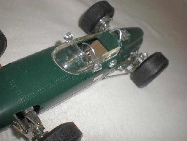
From this angle you can see why a new engine come transmission/greabox unit would be needed.
It was difficult to find a way to mount the car for spraying on a wire coat hanger as I usually would, so I chose to drill a hole in the recess for the air intake trumpet part. This hole would be covered up again later on and I could use a paint brush for handle instead of the wire frame.
After a little thought I realised I would need to handle the body a lot more while making the front suspension. It would be silly to put on the top coat and spoil it with lots of finger prints and scratch marks.
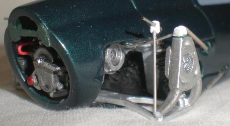
The kit parts were out of proportion and much thick, fabricating a whole new front suspension was clearly going to be an interesting challenge.
First I took measurements from the kit parts and made some rough drawings. Then I tacked in the rear suspension bottom links and measured up the track with the rear wheels and tyres on. This was so I could ensure the front and rear track matched up later. Once I had some plans to work to I made two top rocking arms. They are needed to position the wheel so I had to have them established first. Using stock plastic strip I cut and shaped the rocking arm then repeated the process for the matching one on the other side. They are quite substantial looking in the photos and I also had to consider their load bearing job given that there will be no triangulated support front the dampers and springs which are mounted inboard on the real car. In order to give enough rigidity to hold the cars weight I drilled two holes in the ends of the top arms and in the wheel well in order to mount them with brass rods. This worked very well and gave me the position for the bottom wish bones and hub carrier, both of which I now had to make from scratch.
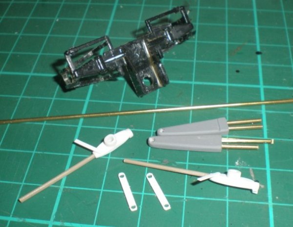
The hub carriers were made from stock plastic rod cut to the size I needed then shaped to match the photos using files and wet and dry. To ensure I got them to look the same I used double sided tape to stick the two parts together so I could shape them together. I drilled the holes while they were still together too so the ride high would be the same. Several dry runs helped me get the brass rod bottom wish bones into place and super glued together and to the hub carrier. These parts were then left to dry and spray painted.
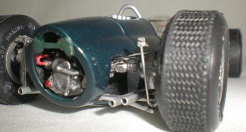
With the suspension parts made I turned my attention to the wheel wells and mountings for the suspension parts. I added stock plastic strip to replicate the longitudinal frame members and some shaped strip for the brackets. The kits rear suspension springs were cut down and sanded in half to give the illusion of the inboard front spring and damper units being in place. I made the radiator pipes to fit into holes drilled in the front wheel wells. They are from aluminium tube covered with masking tape and 5amp fuse wire clamps. They add some detail to the area and make it look a little less empty.
I built in some plasticard ends for the rear tub extensions over the tube spacer and doped paper blanking I had made earlier. A cross member to mount the spring/damper units and antiroll bar links was added too. I had studied photos and see through drawings found on the internet which gave me the basic idea of what I wanted and just copied what I could see. Some filler and sanding finished the area off. Now I could paint the body.


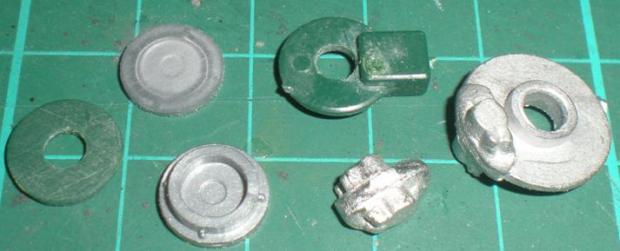
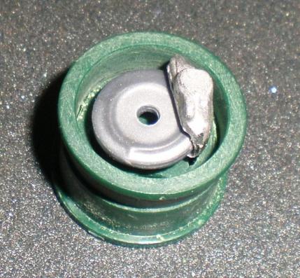
Next on the list of jobs was making some sort of gear box to fill in the back of the bodywork. You can’t really see that much but it still needed something. I hunted through my spares boxes hoping to find something simple to convert but nothing jumped out at me. The kit had a piece to fill in the rear opening but not the drive shaft openings so if I could fit the kit gearbox end onto something that was similar I might be onto something. What I used was a Fire hydrant from an old Revell kit and cut it to fit, added some shaping from Isopon38 and hose end plates again from Revell's fire fighting kits for the drive shaft openings. Universal joints were cut from some old white metal parts and drilled to take plastic shafts later.
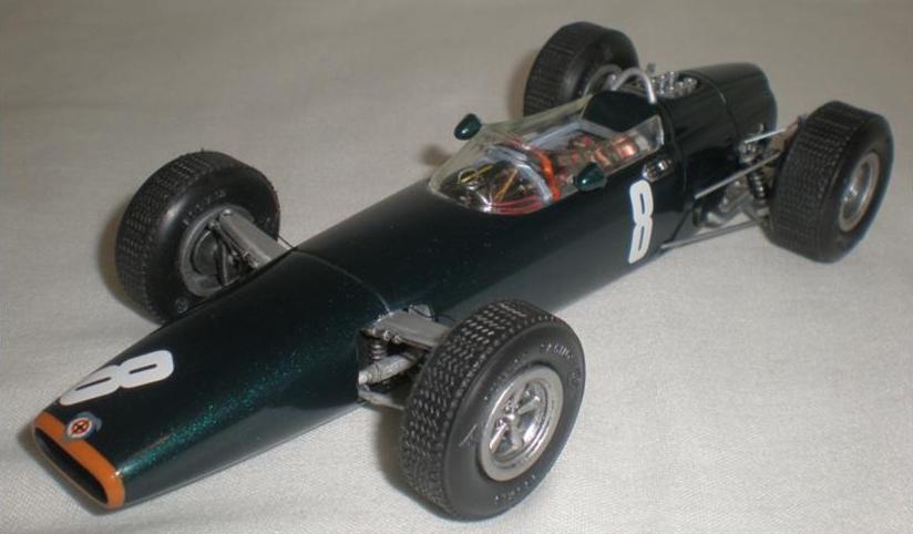
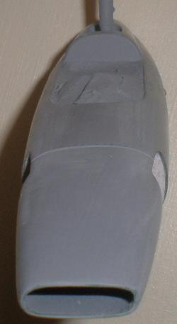
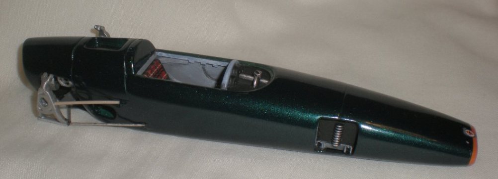
I chose to spray the nose with a coat of Halfords Volkswagen Brilliant orange. At first I thought it was too light but once the Dark green paint went on it looked better. In this case the top coat I used was Halfords BMW Boston green metallic. Several coats were needed as the paint was surprisingly translucent so the orange nose area kept showing through against the grey primer of the rest of the body.
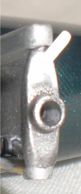
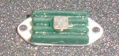
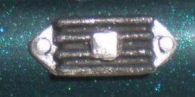
The electrical box mounted below the rear of the cockpit side on the left flank of the car was rather basic and too bulky so I thinned it down and mounted it onto a thin strip of shaped plastic strip. Some photo etched dots give the impression of mounting screws. It was painted with satin black then brush painted with silver acrylic for the mounting plate. The kit part had a nasty ejector pin mark right in the middle which I hid behind a small photo etched square.
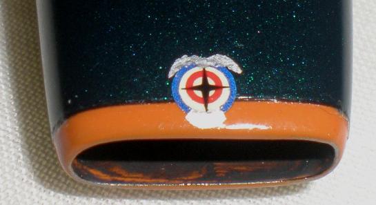
The BRM decal for the nose was made from a series of other decals to give the final touch to the car. Using a multi sizes single punch of the type used for cutting holes in belts or shoes I cut a blue background circle from some old decal sheet. Then using a smaller size I cut the centre out of an autolite decal to give the white and red circles with a four point star over it. The silver bird and name plate were carefully cut from some old silver decal. These were applied one by one over an evening so I didn’t keep moving them while putting the next one on top. Anyway it worked out well even if not 100% accurate not many would know. Once it was all dry I covered them with some clear varnish.
The kit wheels were thickly chromed originally and looked much better once the chrome had been removed. The backs of the wheels were solid and this was not going to do. Slowly I opened out the centre hole with increasing sized drills then by careful filing and sanding. This is more tedious than difficult but worth it for more realism. Now you can see light through the wheels and add brakes. The rear brakes were in the kit although not very detailed and rather inaccurate. I sorted out some old white metal parts that gave better callipers but the discs were too big. So I cut the callipers from the white metal ones and put them onto modified kit parts. For the fronts I needed to go back to the spares boxes and it was old Revell fire hose parts that came to the rescue again. These were sanded down and the centres drilled to attach to the wheels. Callipers were added as for the rear wheels.
I thought the rear suspension was going to be easy as the kit seemed quite good in this area. Just a few details to add, upgrade the springs and dampers, scratch build some anti roll links, nothing much more than putting the kit back together I thought. How wrong? Well I had already reshaped the overly large rear hub carriers once and they seemed fine. When I came to mount the radius rods the bottom was ok but the top was heading up at an alarming angle. This just didn’t look right and meant the top locating arm would also be going upwards from the body at an angle unlike the photos. I studied the photos over and over setting up the radius arms halfway up the hub carriers. This looked better but not right and the top link was still not right. Eventually I realised the kit hub carriers were too tall and I had to cut then down and make new links on top . Fairly simple to do as it just meant cutting off the top, sanding down and adding new shaped parts from plastic strip. Although only a few millimetres lower it made all the difference to the way the parts went together, things matched the photos much more closely now.
The anti roll links were made next. 15Amp fuse wire rolled out straight under a metal rule and some carefully cut and drilled plastic strip gave me what I wanted. Having already put in the cross member with the rear tub bulkhead as mentioned I knew the location holes were drilled ok and could just glue in the shaped wire parts. After slipping on the small plastic links then it was simple a case of trimming some wire to size and super gluing it all in place.
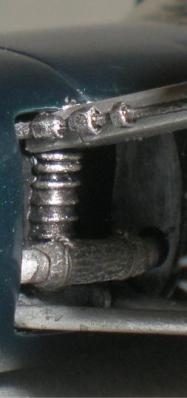
I used some old spare white metal dampers carefully sanded and filled before paining them. Springs were made from fuse wire wound round some plastic rod and spray painted with satin black. The head of the unit was set into the afore mentioned cross member then the body unit sat in predrilled holes in the bottom link below the hub carrier. The body and head of each damper had been drilled so a fuse wire core could be used. This is simply cut to size as needed. The spring is then slipped on and the head super glued in place. The sub assemblies are then slipped back into place in the suspension. The drive shafts were made from some old white metal ones cut down and re-shaped to give the universal joints to look more real, certainly better than the simple plastic shaft that the original kit had. Finally the rear suspension was complete, and it was even more difficult to do than to write!
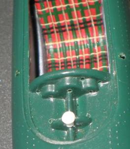
With the car now sitting on all four wheels it just left the final details to be added. To start with I added the gear lever, dash board and steering wheel. The kit steering wheel was a simple thin down and clean up before painting. I sprayed the whole thing silver then brush painting the wooden rim with citadel acrylics over coated with Tamiya clear orange. I was not that sure about a wooden rim but it is clear as day on my period photo. The gear lever was another old white metal left over. I planished the bare metal shaft then gave it a wooden knob using the same paints as the steering wheel rim.
The dash boards had been thinned down and reshaped from the kit part. Photo etched bezels were added over some old style gauge decals. Then Humbrol matt black paint was applied to the dash face. Finally photo etched dots were added for the securing screws and one which was painted with Tamiya clear orange for a warning light. This subassembly was then added to the car and other switches added to the surrounding dash area as per photo references. This consisted of a red push button on the right hand side and two wire toggle switches on a drilled photo etched back plate.
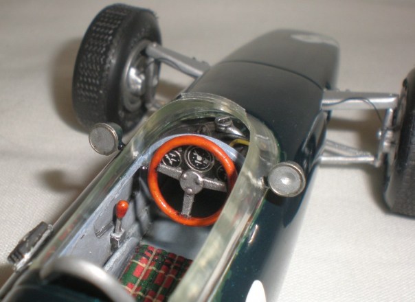
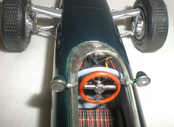
To finish off some wiring was added to the area behind the dash which is very visible. As I mentioned before I didn’t open out this area of the cockpit but the wiring laying over the top helps fill the area and add realism. I used a variety of colours as in the reference photos and different sizes too as some of the gauges are multifunction so there are smaller wires as well as the main one in some of the gauges. With all the switches, gauges and buttons wired up I gave the area a coat of clear matt varnish. Once that was dry I washed it over with some citadel armour wash. Together this gives shade and depth to the area while taking any unreal shine off the wires themselves.
Lastly I fitted the windscreen and rear view mirrors. Clear varnish was used to secure the windscreen while tiny dabs of super glue attached the mirrors.
Conclusion..........
This was a very interesting model to work on. I really wanted to keep it as original as possible but in today’s model world it really needed all the upgrades. However most of the kit parts have been used again and the model stands as a testament to the technologies of its era allied to many years of progress in model making skills and accessories. I am really pleased with the end result, this is a lovely looking model. The P261 was a good looking car and although the model isn’t totally accurate it is a nice replica and very rare. I think it will be a real crowd pleaser at the model shows this year.