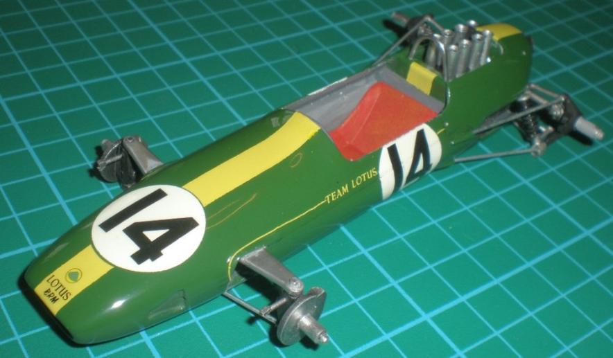
1967 Lotus 33 BRM.
We move on to building a metal model in this article. There is nothing to fear from metal models unless you fear hard work. Metal models always seem to need more preparation and metal is harder than plastic to sand or file, and there are some adhesive issues. Ultimately however you will find that principles of making a model seem to be the same whether it’s plastic, resin or metal.
I chose this kit to demonstrate building a metal model for several reasons. It is 1/24th scale so it will fit straight into the museum displays, it is large enough to add detail to what is now an old kit, meaning you get to see more detailing and building ideas. Lastly, I could add another car to my Graham Hill collection.
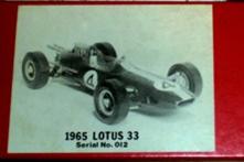
The kit is packaged in a sturdy red box with a b/w picture of the completed model on the top. The kit was previously released by ‘Autokits’ & Wills finecast, this kit (& several similar items) is still available from today South Eastern Finecast.
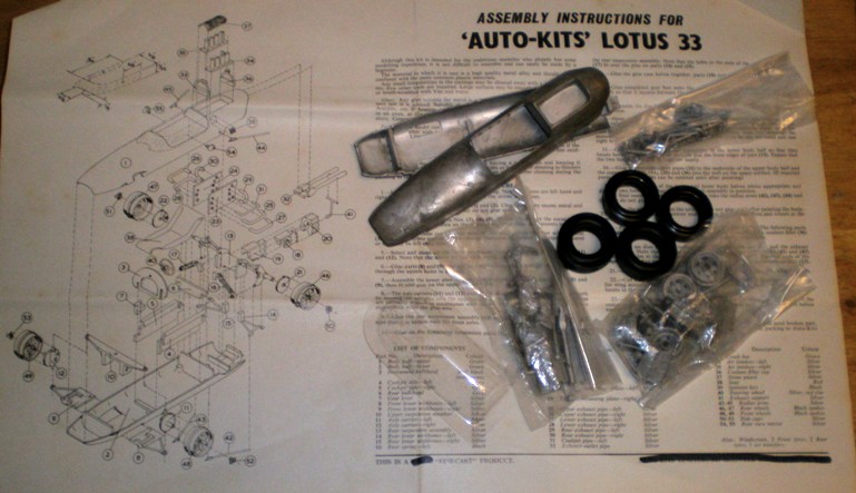
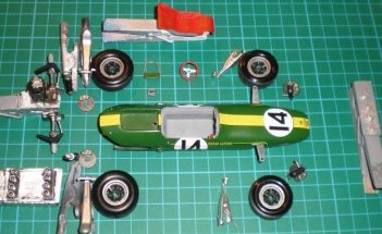
What you get in the box. One clear vacform windscreen (that seems to be rather generic), Two body halves, three bags of parts, four tyres, a decal sheet and instructions.
This type of exploded drawing can be confusing so you must read the list of instructions to find out the build sequence. A point of interest is that although this kit is produced by South Eastern Finecast they maintained the Autokits title and the instructions clearly refer to this.
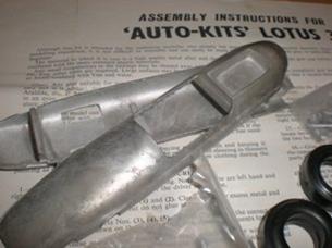
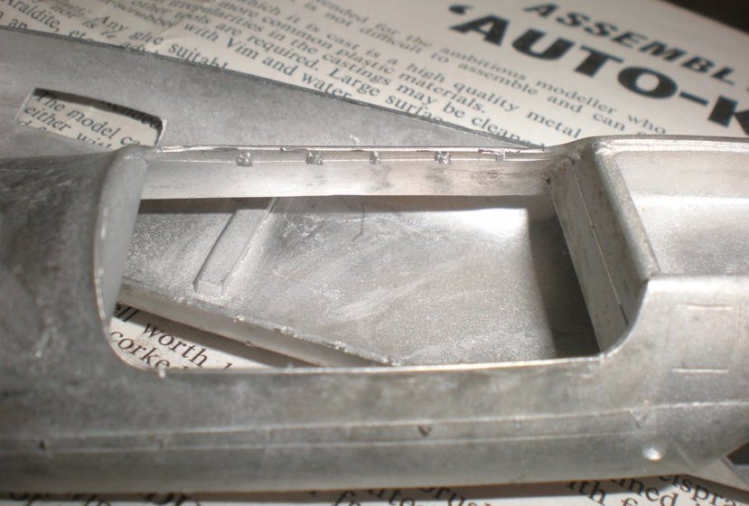
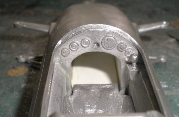
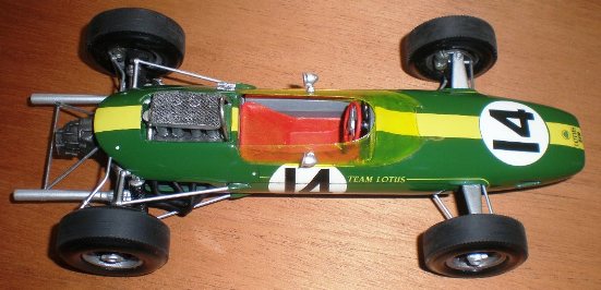
As can be seen here the surface is not as ‘clean’ as a plastic kit. This does happen with metal kits and in this case is probably due to the age of the moulds and any masters still in use. These days there are some very high quality metal kits which will be almost as good as any plastic kit.
Pour marks can be seen along the cockpit edge and on the side of the body. Also visible is a mould line. This mould misalignment will require fillers to rectify not just filing and sanding.
After a long look at the parts and instructions, and comparing them with photos and cutaway drawings I set about cleaning up the body parts, dry fitting some of the sub-assemblies and started to formulate a plan to build the model.
The front suspension was an area in need of much consideration. If you have read our other articles you will know I prefer to put the body together and add other parts after the body finish has fully cured. Like the BRM P261 this was not going to be possible. Much of the front suspension and its openings would need reworking and detailing, some of the cockpit would need to be fitted before the body halves could be put together, and finally the engine and rear suspension would need a makeover to put it in place before the body could be built up.
I previously mentioned the age of this kit and it is clear that the masters have been hand made. However they are actually well engineered. Once they had some cleaning up they went together well and when set into the body were snug and secure.
Dash detail is ok but clearly would need more added later.
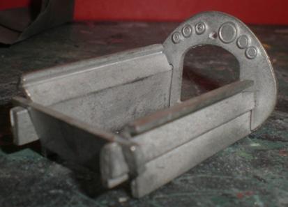
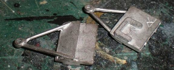
From this dry run I can plan the next step. The pedals mount from a bulkhead that also mounts the rocking arms.
I will build this up along with the rest of the internal tub and pedals. The rest of the cockpit detailing can be done after the body is put together.
Note the Arrow, L and R scratched on the parts. This helps speed up identification and orientation of parts when doing repeated dry runs.
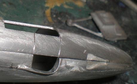
After some deliberation I decided I would detail the front suspension. This was prompted by the design of the front suspension parts that mimicked the real car. If I open the area and build up the tub internally I could replicate the car more realistically and strengthen the model too.
After marking out the area with a sharp blade I cut through using a large razor saw. The metal is quite soft and I had no problems with the “operation”.
The lower front wish bones are just sort of laid onto the body. My plan is to fit the body parts which, also help position the top rocking arms part, then cut off the wish bones to aid me with improving the look of the body and strength of the model.
I can then add some chassis link detail to the new bottom wish bones.
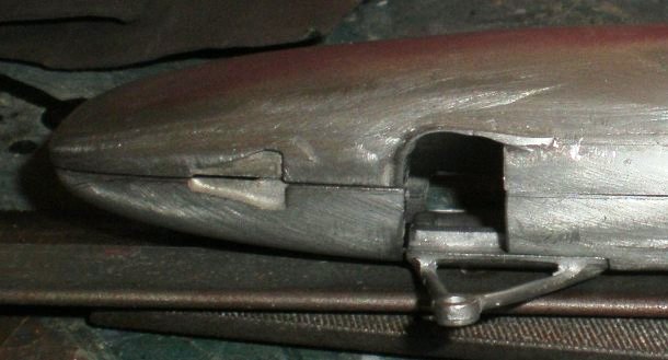
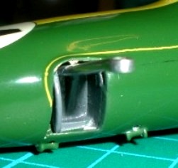
From this dry run you can see how the front suspension area is now open, so a coil over shock suspension can be fitted, as on the real car.
The bottome wishbones will be cut off and then all these join lines will be clear for filling and sanding.
Note in the two pictures of the suspension openings that the body has had a basic sand all over just as I would do with any model kit. The cleaning up and preparation is just as for a plastic kit, though it can take a little longer and you can expect to get very black fingers. Use gloves if you have sensitive skin.
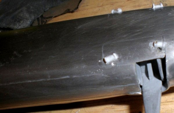
This picture is jumping ahead in the build but it seems appropriate to let you see what the plan is for the front suspension.
The Top rocker arms will maintain proper width of the suspension and lugs and fine drill holes will locate the new botton wire wishbones.
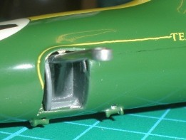
With the body put together in this photo you can see how the join and moulding lines can all be filled and sanded ready for priming and painting.
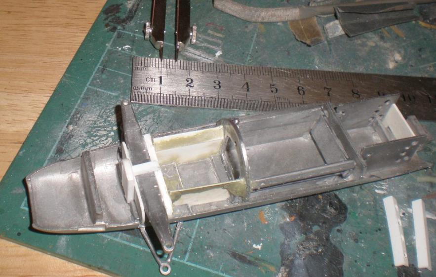
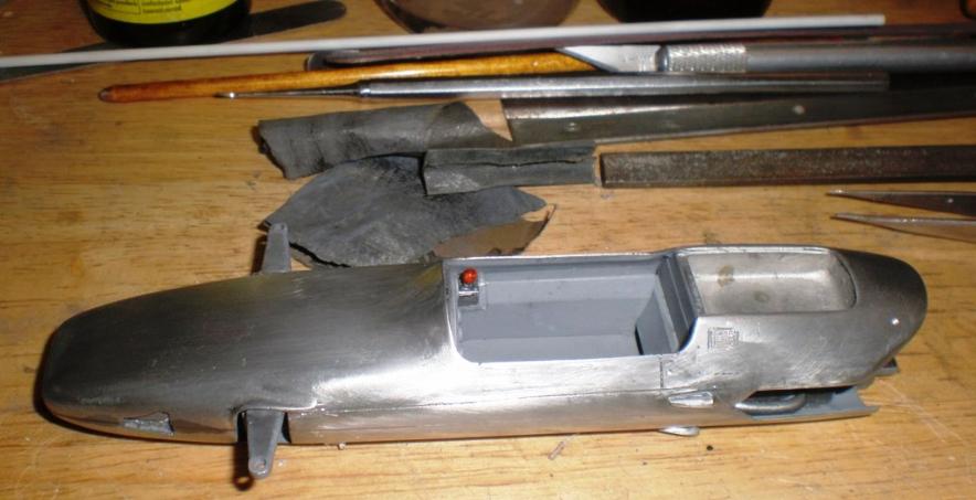
Now we can see the new tub built in the foot well space.This is the kit showing it’s age. What was once an acceptable style of kit no longer meets our expectations.
Also evident is the support for the front suspension which has the dual role of stopping light showing through the model in unreal ways, and being more faithful to the cars chassis design.
The lower wish bones will be cut off, the mountings detailed and new wishbones made from brass rod.
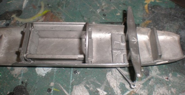
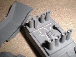
Finally the poor engine detail is evident. Even for the climax engine it isn’t accurate (check the instruction sheet the model’s sitting on). This area will also need attention before we can bring the two body halves together for good. In truth very little of it will be visible so we don’t need to go over board on this area, just enough to fool the eye.
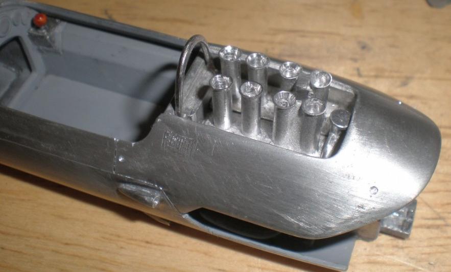
The low exit exhausts for the BRM engine will need the scratch built exhaust exit manifolds in the bottom right of the picture.
To fill out the area below the exhausts one of the kit tube parts was put in place but all the other holes were covered by Trimline tape. It is in no way accurate but once the exhausts are in place they will give the impression of a real engine in the space.
The exhaust heads were made from Evergreen angled strip drilled to accept the pipes which will be scratch built from electrical wire later.
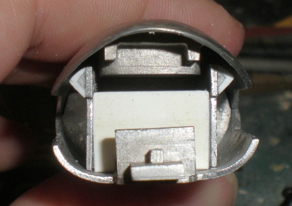
Need to fill the big hole! But how?
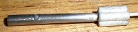
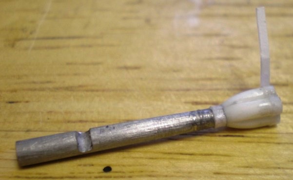
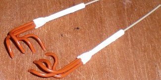
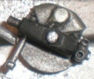
To accompany the new exhaust heads the old kit parts needed a make over too. Four pieces of rod were glued together and attached to the sawn down kit end pipe reshaped and augmented with paper reinforcing strips. 1.5mm electrical wire will be used for individual pipes as it is cored it can be bent to shape as needed.
You can see the process for making the new low level exhausts clearly here.
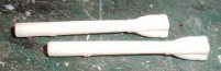
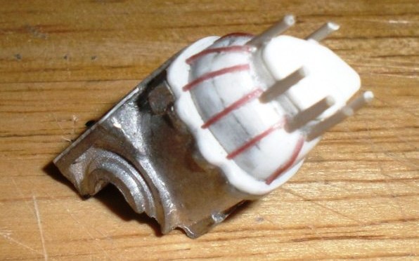
Once one collector and pipe was made it was used to produce a mound from which two identical items could be cast.
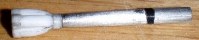
You can see how the electrical wire has been bent to take on the shape of the individual pipes and how they were mounted for spray painting. A coat of Halfords matt black was used over all then the collectors and tail pipes were painted with Humbrol metal cote enamel paint.
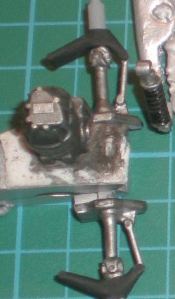
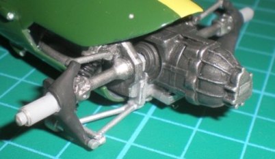
While the engine may have been a basic affair with little of it visible, the gear box was another thing all together. This would be visible and although the kit parts were of acceptable detail level they were for the ZF unit that was coupled to the climax engine for most of the team cars. BUT, I needed the Hewland item as mated to the BRM V8 engine for Graham Hill’s 1967 Monaco car.
Clearly I was going to have to do some more scratch building.
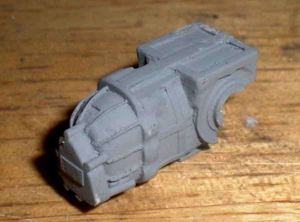
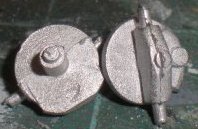
The main transmission parts were mated to a Hewland box cover. A flat piece of plasticard was first put to the metal kit parts and sanded to match its shape. Evergreen strip was doubled up and shaped with sanding sticks for the reducing cover before the smaller cover plate was constructed similarly. Thin plastic rod was cut to produce the reinforcing ribs and bolt lugs.
The Trans axle is moulded in one piece but generally acceptable. In due course more detail would be added from generic photo-etched sets.
Note that some of the cockpit detail has had to be added and painted now. The body needed to be put together to allow removal of joint lines and re-scribing of panel lines.
With new tub sides and floor in the foot well, and the body parts put together we get a feel for why the extra work was necessary. These areas can be seen.
Pedals were made from half round and flat strip, enough to do the job without costing a fortune or expending too much time.
All this work is neccessary so we can join the two body halves together and remove the joint lines. Once the body is together many of these places will be inaccessible or the parts won't be able to fit through the gap to get to their intended position.
This also means the insides need to be primed and painted too!
Metal kits require different adhesives. Two part epoxy “Araldite rapid” is good for the job being much more durable than superglues. Superglue however, is still useful in bonding the smaller parts, gap filling and doing small “tack” bonds to hold parts in place while the epoxy is applied and hardens.
Here the top and bottom of the body have been put together with superglue and Araldite. In some places the joint has almost completely disappeared while in other areas the filling effect of the adhesives can be seen. Other fillers used in preparing the body were Milliput and Tipex!
New panel lines were scribed by shaping old Dymo tape, sticking it in position on the body and repeatedly running the scribing tool along the edge of the tape. Dymo tape is hard and thick as well as self adhesive so it is ideal for this job.
Turning my attention to the front suspension I cleaned off the flash and mould marks from the kit parts then using thin plastic rod and strips of paper I fashioned the steering arms missing from the kit.
Having cut the bottom wish bones off the body and cleaning up all the joint lines I fixed the ring to the bottom of the uprights and drilled them ready for the new brass rod wishbone rods later.
Once painted you can see how seemingly simple things can become convincing model parts.
After that the rest of the useable parts were cleaned up and primed ready for painting. The air intakes were drilled and the roll hoop had the mounting for the old mesh trumpet cover removed. A new intake cover would have to be scratch built later.
The mounting blocks for the rear radius arms were put in place using superglue and tipex to fill any small gaps. Each kit part had the rod cut off and the block drilled ready for metal rod radius arms to be added later. The bottom wish bones and the rear uprights were also drilled for the same reason.
With all the parts now mounted on pegs (by double sided tape) they could be primed and painted.
All the earlier test fitting should allow a speedier build once the paints are dry.
At this point most of the parts are ready for assembly. The ‘Vacform’ screen will take a lot of work and there is still scratch building to do for the front spring and damper units, the front suspension wishbones and rear radius rods, as well as the anti-roll bars.
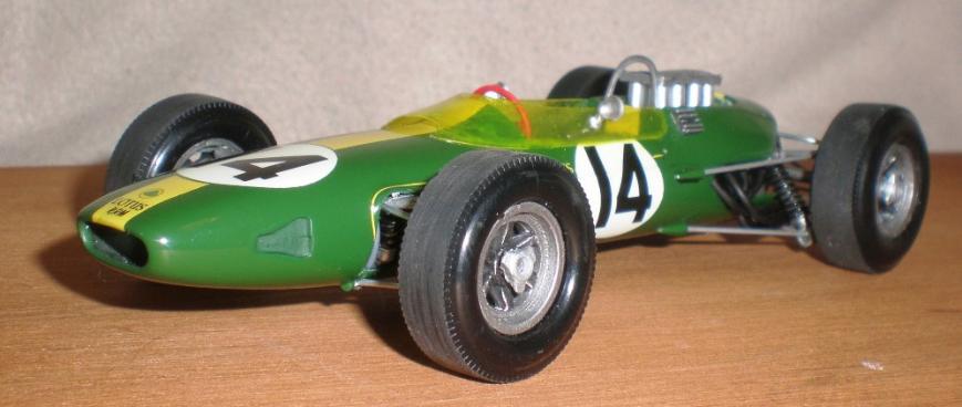
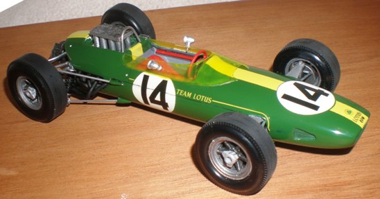
The main body was airbrushed with a mix of acrylic greens, over Halfords primer, it took a little experimentation to find the shade I wanted. A coat of Halfords clear was then sprayed on so the decals could be applied without the backing paper silvering.
Once the decals were dry further coats of clear could be applied (carefully at first) then cut back and polished with normal automotive products.
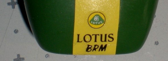
The decals applied to this model are not the kit decals which were far too orange in colour and the text for the ‘Team Lotus’ was the wrong font. Instead the decals from a Tamiya kit were trimmed down to the right scale.
Noting that this car was powered by a BRM engine, rather than the earlier Climax 1.5Ltr unit, the nose decals had to be amended and the BRM letters cut from spare decals that looked to be about right.
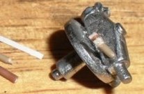
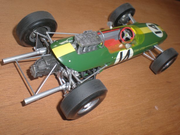
To get the most realistic appearance from the different metal parts they were painted with different shades of chrome, silver, Gun metal and chainmail. Then differing shades of ink washes were used to further pick out detail and add realism.
With the addition of dry brushing the final look of the drive train is quite pleasing.
The exhausts must now be confronted and they are a rather daunting prospect at the moment.
There are limitations with this kit and eventually one has to realise that only so much detail can reasonably be added. You can always go the whole way and add every detail but this inevitably means the build will take much longer.
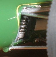
To fill the void in the front suspension opening spring and damper units were scratch built from tube, rod and wire. Once in the y replicate the real parts quite effectively.
Adding the suspension was straightforward following the kit instructions and carefully adding metal rods, painstakingly test fitted and adjusted, for the lower front wishbones and the rear radius rods.

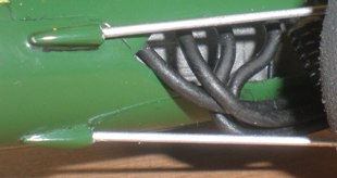
You can see how the electrical wire has been bent to take on the shape of the individual pipes, then they were spray painted.
A coat of Halfords matt black was used over all then the collectors while tail pipes were painted with Humbrol metal cote enamel paint. Effectively scratch building the exhausts was not as difficult as had been foreseen and the final result is pleasing.
The exhausts extend back further than they should due to an incorrect measurement on my part, putting it simply the individual pipes and 5mm to long (need to be 27 mm for those who might like to have a go at the conversion themselves).
The antiroll bar was simply made from metal rod, bent to shape and super glued in place
The wheels and disc brakes went on without incident. It is a testament to the engineering of the kit that however much we think kits have improved this kit put four wheels on the ground first time out. The hub knock offs seem a bit over scale but not having any suitable replacements and short on time they were pressed into service regardless.
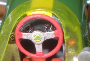
Moving onto the cockpit the Dash board was picked out with citadel paints and decals from the Tamiya Lotus 25 kit added to the dials. Decal setting solution (Microsol) was used to settle the decals which conformed very well. Once dry a coat of clear matt acrylic varnish was applied overall to seal the decals down. Gloss acrylic varnish was later used to pick out the dial faces.
All together a pleasing effect. More switch detail could have been added but the build time was extending too much!
The vacformed screen was not an easy part to work with having little in the way of demarcation one works according to the measurements on the instruction sheet. It took a whole evening of repeated dry fitting ,offering up and trimming, to get anything like a useable windscreen.
It is secured but tiny drops of superglue in strategic places and then thinned ‘Gator grip’ run along the join.
The yellow effect is achiever by mixing clear varnish and yellow citadel ink. On this occasion it was applied by brush. Had this been a more solid plastic part requiring less handling then airbrushing would have been a better method of application.
The final detail was the mesh cover over the intake trumpets. Having been told some time ago that these items could be a little crude at times, and noticing that the mesh cover on the BRM engine car is none standard, a new part was fashioned from fine photo-etched mesh (available from Renaissance) cut to size then the edges folded up and silver tape put around the edge replicating the frame.
So to summarise the differences between building a plastic kit and a metal kit:-
Metal kit parts are more messy to clean up,
You may have to do a little scratch building,
You may have to deal with vac-forms for the clear parts,
You will need different fillers,
You will need different glue, and,
You must take your time, test fit everything.
As with the resin kits they’re really not that different at all.
More pictures and information on this car can be found in the Graham Hill Collection.