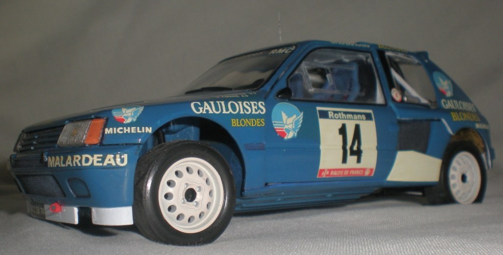
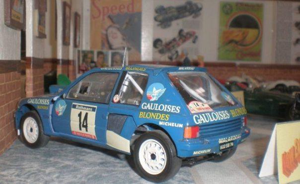
Detailing a Peugeot 205 T16 by Ian.
A new breed of rally car that came from a new form of road car. The Hot hatch ruled the streets and took it’s superior attitude onto the Rally scene too.
I obtained this car (along with several others) at the 2009 Scale Model World show from the “give a model a good home” sale.
The kit appears to be the 1/24th scale Heller version, kit no 80716. It is a fairly basic kit, featuring some over sized mounting points and some parts that seemed to “snap together”. The model was quite well finished and had been augmented by the addition of an aftermarket decal sheet (studio 27 set ST27-DC709C).
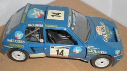
1/24th scale 1985 Peugeot 205 T16
tour de corse
Research proved my suspicion that this was a rare colour scheme. I only found a few pictures of the actual car so had to work from a collection of images for an overall representation.
This kit is never going to build into an totally accurate model so here I am just in search of the illusion of reality while demonstrating some ideas and techniques for improving a model.
My first job was to get a coat of polish on the body parts. This is to clean up the body, check on the quality of finish, and to provide a level of protection against handling and slip ups with the paint brush. I should caution you to check carefully that the polish you choose isn’t going attack the decals as I have had this happen in the past. Next I planned the things I wanted to change or add. I spent a while considering this as things like the one piece flat dash board represented simply by a decal beg to be replaced, but, it would not be possible to go to these lengths without taking the car to pieces or putting things over the decal, all in all it just wasn’t worth it.
My research did show white paint on the inside of the body panels. Rallying is not my main area but it seems reasonable to assume the car was supplied in the Peugeot white of their race team and then the external body was over sprayed in the purchaser’s new colour scheme. This meant painting the interior of the cabin and engine bay white. This of course had to be done by brush as it would be impossible to mask up all around the body parts ,windows etc to spray. Using citadel acrylic greys and whites I built up a good level of colour and shading, this is done over a series of thin coats applied with plenty of drying time in between.
This meant painting the cabin interior and engine bay white, and this would have to be done by brush as it would not be possible to mask all the body parts, windows etc to spray.
Using citadel acrylic greys and whites I built up a good level of colour and shading, this is done over a series of thin coats applied with plenty of drying time in between.
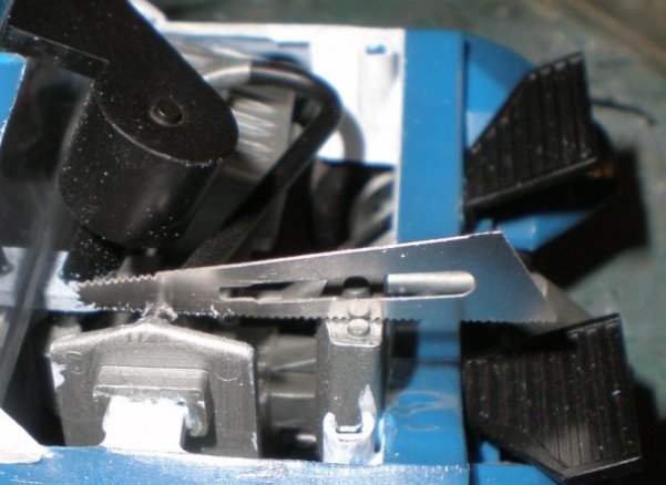
The cabin interior was updated with an ever growing list of additions. Firstly some scratch built pedals, these are simple to make from plastic strip and rod. Honestly, they are easy, as with any scratch building you just need to take your time and the keep persevering.
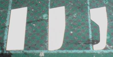
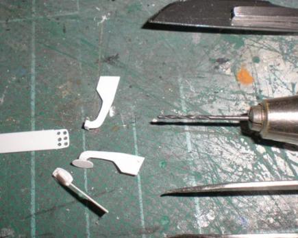
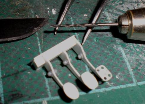

Starting with some evergreen strip I cut out the basic shape and sand down to the final shape I want. Repeating this process twice over. To make sure I get them all the same I just lay them on top of each other while measuring and cutting each one out. If needed I use double sided tape to stick them all together so I can sand and file them all at the same time. The photos suggested differing shapes for the pressure pad areas, so I had a little more scope for mistakes. I used evergreen strip cut to length then shaped with some sand paper. A pin vice and micro drill bits were used to give the weight reducing drilled out look. Mount the pedals to a backing strip and support them with some small squares of rod.
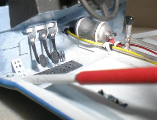
A fire bottle from the spare parts box was slipped in according to photos of a Peugeot team car. Small strips of plastic card were used to make the mounting bracket. The same team car pics showed other electrical boxes and wiring so I added a few bits of wire and modified some parts from the spares boxes. The wiring is fixed in place by feeding them through some larger diameter tubing to keep it all tidy then these are fixed in place with super glue. I always like to add a bracket or some form of mounting for things, even if it’s cut up masking tape. You’d be surprised how much of race cars end up being “Gaffa” taped in place!
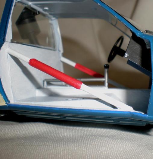
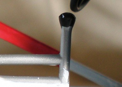
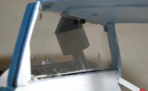
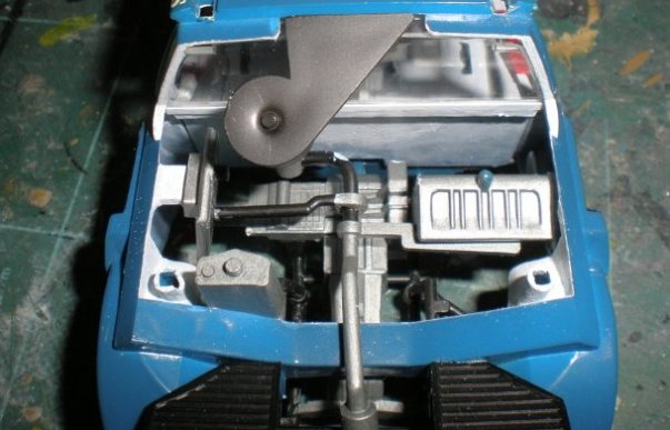
The main feature in the centre of the cabin is the gear lever linkage. It is very plain in the kit but with a few simple additions could be made to look much more realistic. Any lever is going to need a mounting point so I cut two small triangles from plastic strip and then carefully sanded them to round off the angles, to these I added some hex’ nut & bolt parts from the "Model Dr’s" range.
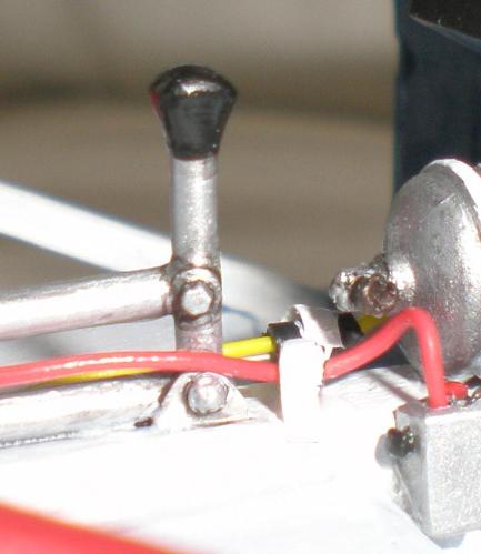
These "Model Dr." NBWs (nut bolt and washers) are great for adding details in loads of areas in cars and come in lots of differing sizes. Similar products are available from Grandt line but they are for railway modelers and the nuts are not always hex’ but square. I bought loads of these sets ages ago from both ranges because they can be used in so many places and you always have loads in a pack. They can be a pain some times as they can do the disappearing thing if you’re not careful when cutting them off the sprue or holding them in tweezers, but they are worth the effort for the effect they give. I also added NBWs to the upper link. Immediately this starts to look more impressive so once some paint and ink washes are applied the whole area looks more realistic. To hide the rear end of the gear link part I made a simple tunnel from evergreen strip.
Initially Protec was the medium of choice for attaching small parts like these but now it’s unavailable a friend suggested the Vallejo range gloss varnish which does the job just as well. I have taken to this method because it is less messy than super glue, allows some positioning of the part, is clear so doesn’t show if you use a bit too much, it can be easily soaked up with a brush or tissue and it doesn’t attack your paint finish. All this means it is ideal for attaching clear parts or small photo etch parts. It takes around 10 to 15 min’s to dry and contracts as it dries so a little dot used to attach a bezel on a dash board will shrink away to be unseen.
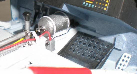
Foot rests and none slip pads were fabricated from plastic card. The hard part here is getting all the holes equidistant. I do this by measuring and marking out with a sharp blade to achieve a grid. Do this lightly then rub in a little dark paint or ink. Use a blade tip to start each hole so the drill bit doesn’t slip when starting off. Start with a small drill bit then enlarge them over two or three increasing steps up in bit size. This also gives a chance to apply a little pressure in differing directions if you notice a hole that’s a little out of line. Sand the surface to remove the grid pattern with a fine sand paper or better still work from the back of the part in the first place. However, this can be a mind bender if you’re working to a shaped part, many a time I’ve finished a part only to realise I’ve done it back to front!
Noticing that the rear window didn’t fit very well I had to add some 1mm strip inside and out to hide the gap between window and the rear cabin wall.
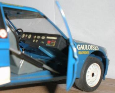
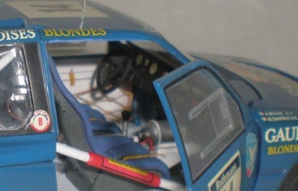
The doors were very plain and needed some detail adding. The door pocket and top window edge frame were made from plastic card and strip. The netting on the door interiors for holding gloves, headsets etc was made from onion bag net super glued over a frame of old household wire.
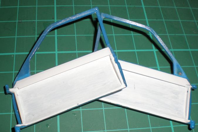
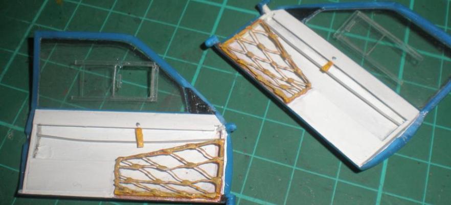
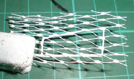
Several coats of paint helped colour the nylon onion bag. Washes of differing shades helped to give a worn and dirty look. The pull straps for closing doors were made from material left over from an old seat belt set. The door catches are operated by pull cords which I represented with the help of some old wire.
To manufacture door windows I use a paper template transferring the shape to clear acetate, cut it out and repeatedly trimmed and sanded till it fits snugly. This isn’t hard but takes time. Once the basic shape was attained I needed to deal with the sliding windows and apertures. I decided only to open one up to save a little time. All the measuring and drawing was done on the paper template then transferred to the acetate. Thin strips of acetate gave the frame and interior handles while the actual slides were cut from a thinner sheet of acetate from some packaging. This gave the impression of depth I was looking for.
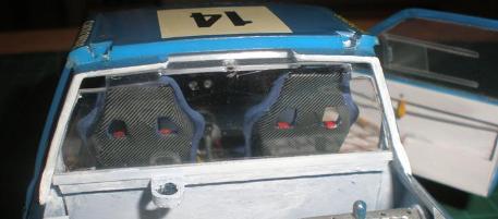
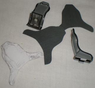
To improve the seats I chose to add some carbon fibre decal. I later found a picture which suggested this should have been the Kevlar yellow brown rather than the grey black carbon type. Any way I needed to start with a template of some sort. I did this by wrapping paper around the seat and doing a type of brass rubbing. This was then transferred to the decal sheet and cut out. I tried to be clever and save time by doing this all in one go but it would have been better to make individual shapes to cover parts of the seat as I ended up having to cut the decal lots of times to get it to settle around all the compound curves. I used some humbrol enamel matt blue brushed on for the seat cover colour and dry brushed on lighter shades of citadel acrylic blues to give some highlights to the seat..
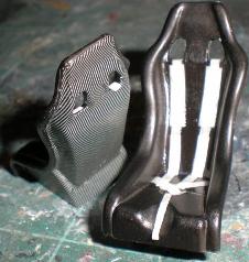
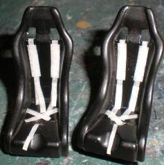

Turning my attention to seat belts I didn’t want to use up an expensive set of photo etch buckles for a car that isn’t my main area of modeling or for seats that are tucked away inside a cabin. So I decided to see how good a result I could get by using masking tape and decal parts left over from other kits. To start off I laid down a strip of masking tape then cut several equal sized strips. These were then cut to random lengths and applied to the seats. Thicker strips were added for the shoulder padding and thinner strips for the crotch belts. Citadel red acrylic paint was used for the belts which were shaded using their range of coloured inks and then highlighted with some orange.
Cutting the seat belt hardware away from the seat belts on the decal wasn’t as hard as I thought it would be. The buckles and fasteners were applied as decals but the adjusters for the shoulder straps were left on their backing paper and painted up to help give some depth. Sabelt logos were added from my decals spares and also to the padding on the cabin roll bars. All of this work was carefully covered with matt acrylic varnish.
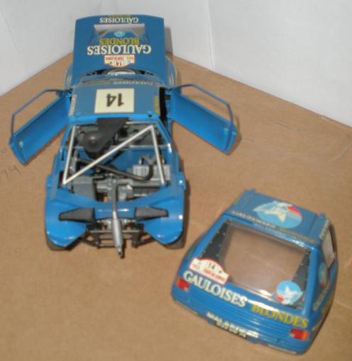
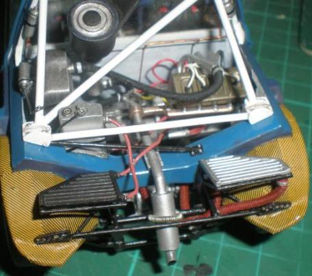
Having spent an inordinate amount of time on the cabin I really had to think about what I was going to do in the engine bay. I found several pictures of Peugeot team car engine bays but from different cars, and each one seemed different to the next. The kit is rather short on detail and accuracy in this area so I had to settle for a sort of generic representation from the photos. I never intended to go as far as I did and in the end removed much more of the engine parts than I intended at the start.
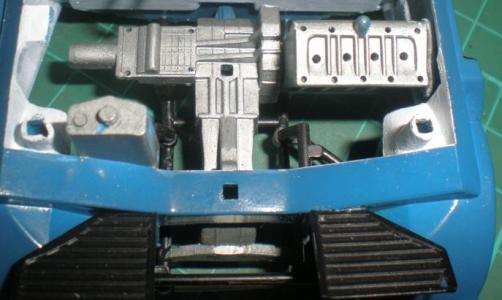
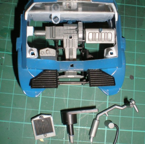
After cutting out the radiator and pulling off the exhaust part, I fiddled the air intake off and separated the hoses from the filters and manifolds. This gave me much more room in the engine bay so I set about improving the grey white interior colouring.
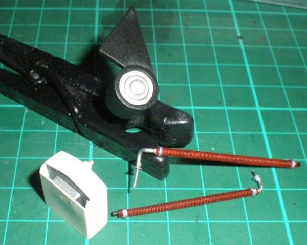
In order to refit the radiator accurately the first thing I did was to drill a hole in both the radiator part and the former mounting ensuring they could be lined up with a simple pin. While I had the drill bit out I drilled small holes for spark plug leads, NBWs on the rocker cover and gearbox top, feed pipes and vent tube from the reservoir and holes to mount the other radiator hoses. Planning ahead a little I drilled the holes needed later for the rear brackets that hold the small “flying” radiators.
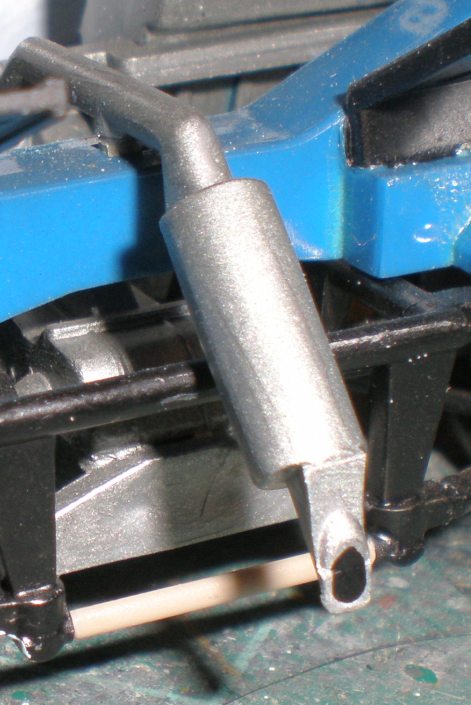
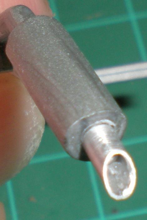
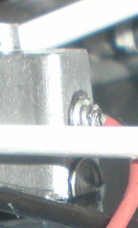
The exhaust was poorly designed as at both ends of the silencer there were extra moulded shapes that shouldn’t be there. The outlet end was simple to deal with (as I was replacing the end with some aluminium tube), I simply cut it off. The other end needed some careful cutting, filing and sanding to make it look more realistic.
Dealing with aluminium tube is fairly straight forward, I cut it in the same way as plastic tube that is to say by rolling it repeatedly under a sharp bladed knife, (firm blade like an exacto and not a scalpel which is too flimsy and might brake and fly off!) the part can be shaped with files and then thinned down to give a scale thickness at the end. The securing spring clip for the exhaust was made from fuse wire wrapped around a thin piece of rod, slid off, then attached to the cross member underneath. It is fiddly but quite straight forward.
Studying the air intake showed the kit part to lack detail. I raided the spares boxes for things I could modify to add detail. A drinks bottle holder from an old bicycle kit gave me a suitable ring, a photo etched pulley face and some shaped plastic rod provided some centre detail and a locking knob handgrip. Looking at the intake scoop and finding it solid I set about but opening up the area to provide a more realistic look. This means scribing away at the area I wanted to remove. Repeatedly cutting in then slowly scraping out the centre gives the depth of opening needed. It takes time and patience, and not a little care, but the result is worth while.
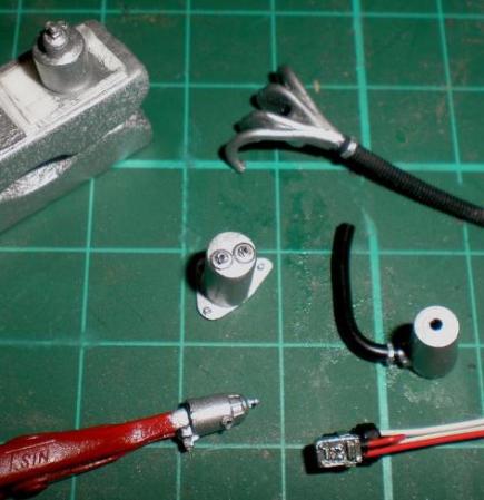
The hoses for the gearbox oil cooler were made from soft resin hoses obtained years ago from renaissance. I drilled them out in order to add some wire mounting parts, and then wrapped some silver painted masking tape around the ends for the jubilee clips. These wires could be fed through cored-drilled NBWs from the Grandt line range to give a realistic but simple hose fitting. The same cored NBWs are also use along with brown wire provided the hoses for the water cooler radiator.
The main intercooler radiator was way too thin in comparison with all the photo evidence so using plastic strip and card I over skinned the kit part and used some isopon P38 to fill in the shaped area. The raised areas that mark out the radiator honeycomb was made from carefully measured and cut Trimline stripe. Trimline is like plastic self adhesive tape in a variety of widths all on a roll. It is more often used by radio control modellers for detailing their models, aero planes or cars. This was also used to make the mounting frame for the reservoir, aided by some NBWs, and provided the rubber straps that secure the reservoir and small radiators. Hose mountings were made from evergreen plastic rod.
I made a simple distributor with electronic ignition box attached in order to give the car some spark plugs. Followed by an alternator and water pump, some simple reservoirs and all the necessary mountings. When it comes to scratch building these sorts of things all you need to do is study the real thing, identify the shapes in it and fabricate them. Then put the shapes together.
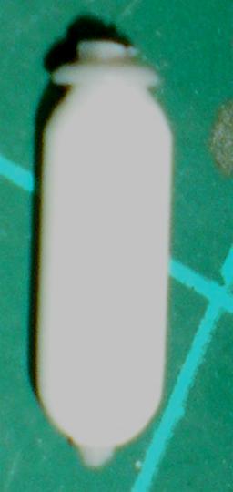
The small reservoirs were made by putting a small length of rod into my mini motor tool to use as a small lathe, at low speed, and sanding the end to shape. Then swap ends and do it again. A cored NBW at the top and other NBWs as needed for details. Brackets or mounting straps were made as needed. Once made and painted I could mount the ancillaries to the engine and in the bay. Plumbing in could then commence.
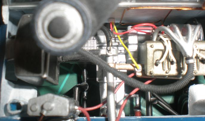
The turbo intake manifold was given a few details in the shape of NBWs and sensor wiring. The header tank appeared to have a sort of site glass on the side which I replicated with photo etched part from the Rai-ro aircraft cockpit sets. I have collected a number of various etched sets of shapes over the years and they often provide useful odds and ends like this. One such generic set also gave the filler cap too. The vent tube was simply made from thin copper wire but this time the nut was made from plastic card using a historex hexagonal punch and die set.
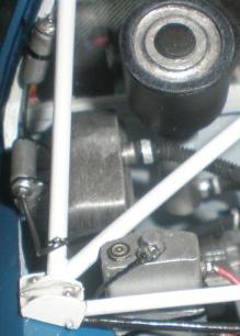
The engine bay was starting to take shape now. The turbo intercooler radiator hoses were also made from renaissance soft resin hoses but of a larger diameter. I treated them in the same way as before. With all the other hoses pipes and wiring attached I could replace the air filter and roll bar.
Studying the photos showed that there were bars missing in the kit and that they were mounted to a plate on the chassis. This meant I could hide the oversized mountings on the chassis. I set about scratch building these plates from evergreen strip detailed with "Model Dr." NBWs. I did note that all the different cars in the photos seemed to have different arrangements of rollover bars and braces. In this instance I could see what the car I was modelling had so I followed that.
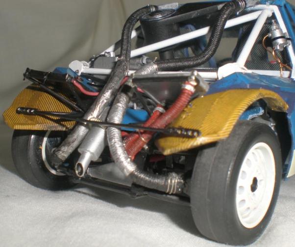
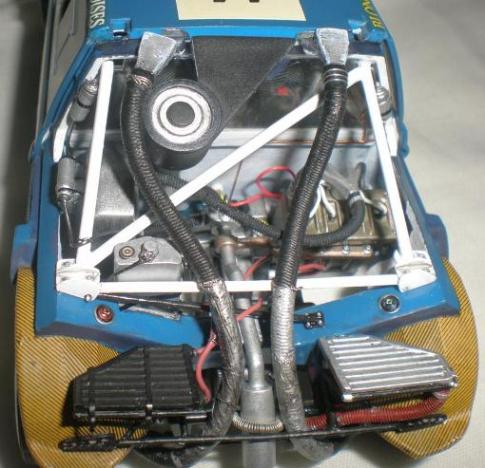
Moving further back I started to look at the rear mudguards and radiator mounting frame. Some old carbon Kevlar decal was used to cover the mudguards. This proved to be very time consuming needing lots of strips to be cut and applied bit by bit to get reasonable coverage. Once they were all dried I covered them with several layers of matt varnish. Having already drilled the holes for the rearward extensions of the frame I fabricated the brackets to mount to the mudguards. Using evergreen strip I cut two pieces to length then shaped them and drilled them using the method outlined earlier. Triangular horizontal parts were then cut and added to these, the cross member made from plastic rod was then added and the assembly attached to the mudguards. The rearward mounting bars and the diagonal bars were then added. Carefully shaping each part to fit snugly. This gave me the horizontal aspect of the frame, time to move on to the radiator mountings. Each frame was made to fit piece by piece and then the whole thing was carefully brush painted in situ. The right side radiator was repainted in silver following photo references. These then had their rubber straps added made from Trimline strip. Silver paint was dotted on to represent the press stud fasteners.
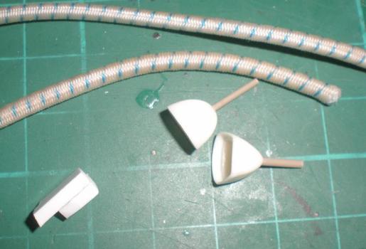
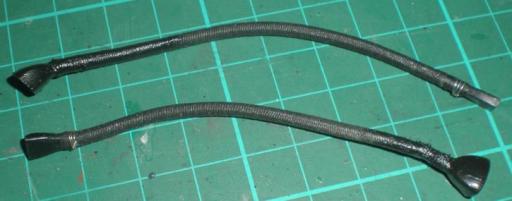
Final work in the engine bay was representing the air scoops and ducting down to the rear brakes. This is evident in many of the photos and the one of the ‘85 corse car. The air scoops were made from thick evergreen strip. I cut one to the rough size and shape I wanted then using double sided tape stuck it to another piece of strip progressively cut that one to size, shaping them together. With the scoop ends opened out to match the main air intake for reality I painted the parts with citadel greys. Having no outlets for the other end of the ducting I trawled through the spares boxes finding a pair of rear view mirrors formerly from the 1/12th Tamiya Honda kit. With a little fettling they were the perfect size and shape to blow cooling air over the rear disc brakes. The ducting itself came from old Revell fire engine kits. The problem is that it is woven fabric over a rubber core. This gives it flexibility but frays at the ends. My solution to this is to soak the end in super glue as soon as the cut is made, this binds it all together and then allows a certain amount of sanding to shape the joint of the scoop and outlet to the ducting. Having joined the outlet to the ducting a sprayed them with Halfords satin black. This would be durable enough to take all the handling and posing needed till the parts took up their final positions on the car. Checking the lengths a found I had overestimated a little and several trims and touch ups were needed till the ducting fell as it does in the pictures. The joints were detailed with matt black paint to represent some tape then fuse wire bindings and a follow up coat of matt varnish over the joint to help hold the binding in place for years to come. The heat shielding was bare metal foil. The ducting was secured at the ends with pins and superglue. I used fuse wire to secure the ducting to the cross brace of the roll cage.
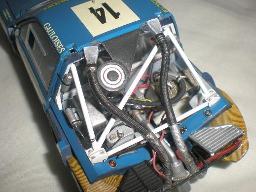
To help the foil stay put in the future acrylic silver paint and matt varnish were mixed together and applied over the foil. A wash of armour ink helped give the light and depth shading. This area is puckered up on the photos so in the end they look quite good.
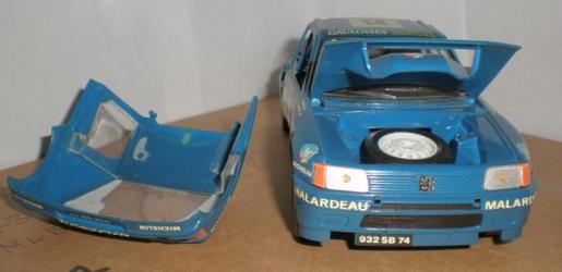
On the out side there wasn’t much to do. An aerial was made from old telephone wire. I left on a section the sheath for the mounting case then super glued it into a pre-drilled hole. Some white decal was applied around the bottom of the front air dam to match the research photos. The over sized mounting points for the missing front light pod were the biggest upset on the outside. It just wouldn’t be possible to cut down and fill then reshape this area without spoiling the existing finish so I decided simply to disguise them with some photo etched shapes and paint them satin black. Now they look like rubber plugs for a pre-existing mounting.
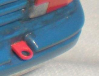
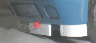
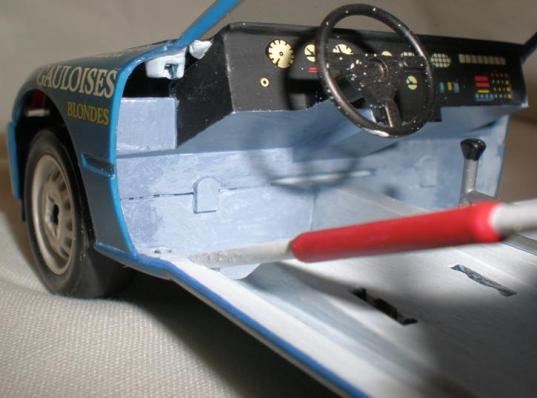
Towing eyes were scratch built from plastic strip. Simple to do by drilling a hole through the strip, shape around the hole with sand paper and cut off to the length you want. Attached with super glue and painted red.
In conclusion.
This model was rather more time consuming than intended, but then, most scratch building takes time. That said these little upgrades are not beyond the average modeller willing to have a go. Of course it is easier to do while building the kit from new. Have a go, with a little practice your confidence will grow.