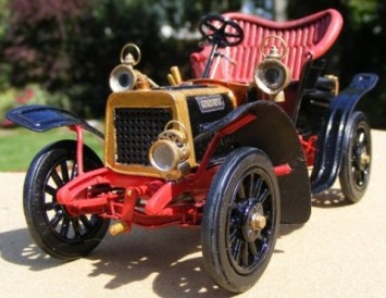
Scratch building ‘Genevieve’, a 1904 Darracq.
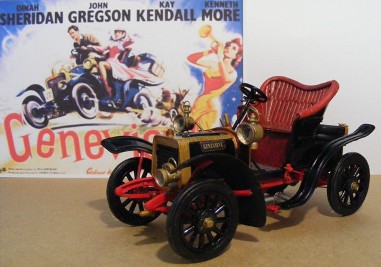
As a further example of scratch building, and so you can see more practical applications, we will take you through the building of this 1904 Darracq made famous in the film “Genevieve”.
The Darracq was one of the first (if not the first) cars to be modelled by AIRFIX in the series of vintage and veteran car kits issued around fifty years ago.
It was one of the early cars rod built and he was very happy with it at the time. But with the Museum display being in 1/24th scale Rod felt he needed to have this car in same scale. Saddly no kit is available so he had to set to work on scratch building one.
Research is always the starting point in this sort of project and in the January 1954 issue of the MODEL MAKER Magazine Rod found a set of drawings and instructions for building a 1/12 scale model of ‘Genevieve’ using "Balsa wood, Bristol Board, paper and other materials" that were used for modelling fifty years ago. Rod re-scaled this drawing and built a 1/24 scale model of Genevieve using to-days materials.
The Build.
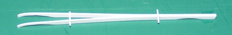
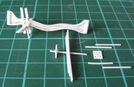
The Floor and Chassis Beams.
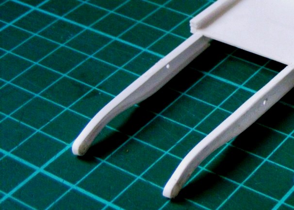
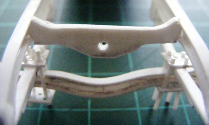
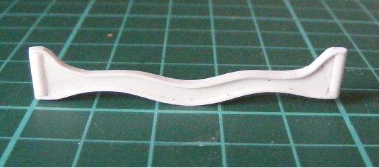
The floor and chassis unit consists of a rectangular sheet base with two identical side beams extending each side. To represent these beams Evergreen 138 strip, 4.8mm wide was cut to length and drilled at the rear spring shackle and front mudguard stay locations. By inserting a short length of rod through these holes both beams could be held together and shaped simultaneously.
The beams are secured beneath the Floor, supported and spaced from the outside edge by a lengths of Evergreen 124 strip, 2 mm plastic strips.
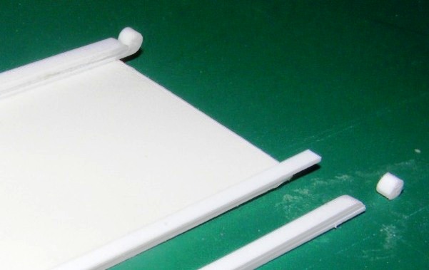
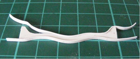
On top of the floor running parallel with the edges are wooden body beams with decorative scroll ends at the rear. On the model these beams were made up of four tiers of .Evergreen 124 strips 0.5 x 2mm wide, laid and cemented together, they replicated the square section beams. At the rear end the tiers of strip were stepped and then tapered by sanding. The bottom strip, that attached to the floor, was left longer than the others this was so a small piece of rod could be transversely affixed to represent the scroll end.

The Dumb Irons.
The real chassis side beams are channel sections but on the model this is only visible over the section between the dash board to the dumbirons. To achieve the channel appearance strips were attached to the top and bottom of the chassis beams flush with the outer faces. The upper strip is bent down at the front of the dumb iron to retain a small piece of rod and then secured under the chassis where it meets the lower strip. The whole channel beam was then sanded to a finish.
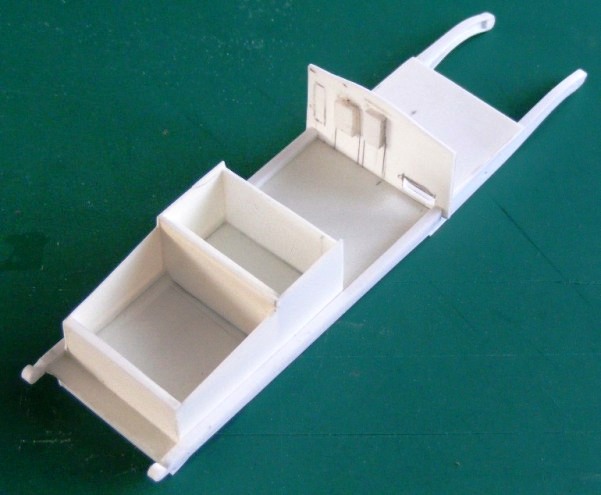
The Rear Body Work.
The seat base and boot is a box section unit with a lid that slightly overlaps the boot sides and rear.
The dashboard was shaped to fit between the chassis members and so also act as a chassis cross member but it was not secured at this stage to allow detailing later. The forward floor section was cut to size but that too was not fitted at this time, being attached later directly to the bonnet unit.
The Seat and Upholstery.
The seat base and a tapered front panel fit onto the bodywork box and provide the foundation of the seat. The back was the most difficult piece to shape being flared and curved. The pattern included with the article did not fit calling for a new template and repeated shaping and fitting until correct. The wing pieces made from the drawing fitted surprisingly well. The upholstery panels are half-round strip cut to length, shaped and ‘dovetailed’ together. The surround is plastic sheathing from electric cable split longitudinally and fitted over the edge of the seat and upholstery panels. The driver’s seat cushion is thicker than the passenger’s cushion but both were made in the same way with a shaped thick base, an identically shaped but thinner top piece and a very slightly larger but even thinner piece sandwich between the top and bottom pieces. The bottom layer of the drivers seat cushion was hollowed out and while the adhesive was still soft the top two layers were pressed well down, to give a ‘sat on’ look. When set dry the edges were sand to contour with the extra thin middle section left slightly proud to represent the sewn seam. The cushions were then put aside for painting and attaching later.

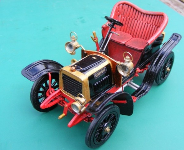
The Bonnet, Radiator and Forward Cross Member.
With the chassis completed and the dashboard available for dry fitting, work on the bonnet and front floor section could be started. The bonnet ‘skin’ is supported on an ‘eggbox’ structure consisting of four transverse formers and a central former placed longitudinally providing rigidity and preventing the thin sheet hood from ‘sagging’. Former No.1 fits behind the radiator and No.4 to the dashboard, Nos. 2 & 3 are positioned equidistant between. An additional identical former provided the back piece of the radiator shell and also provided a pattern for making the grill frame.
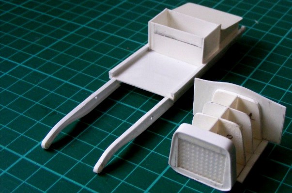
The grill itself is a piece of nylon fabric mesh as is used in making ‘cross-stitch’ mats etc, the radiator surround was formed from strip jointed out of sight beneath the radiator.
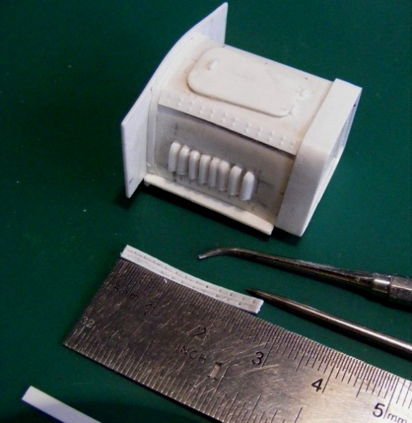
A length of evergreen strip is attached running over the bonnet and butting up to the Dashboard. The brass strips that are riveted and run along the top edges of the bonnet are Evergreen strip marked out on the back with aligning marks scribed on and indented with a metal knitting needle sufficiently to resemble the rivet heads when viewed from the front face.
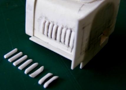
The bonnet louvers were formed from Evergreen ¼ round strip in 6 mm lengths. The ends were sanded round and the right angle surfaces hollowed and sanded out, the result is pleasingly acceptable. The inspection lid, radiator filler and bras wire lamp brackets were added to complete the unit.
The contour of the bottom of the completed radiator unit provided a pattern to produce the chassis cross member that fits between the side members and supports the radiator and the starting handle. The complete bonnet/radiator/dashboard unit is carried on an extended floor section.
The Front Axle.
The axle was produced from a wide strip of plastic and shaped as per the drawing. The I-beam profile being achieved by attaching strips along the top and bottom edges, not an easy job, but pre-curving the strip in the direction required does make it easier. Lengths of rod serve as the kingpins.
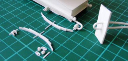
The Front Springs.
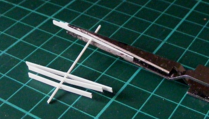
It is virtually impossible to reproduce exactly in plastic a set of leaf springs to 1/24 scale as you cannot obtain strip plastic of the correct thickness, or more accurately thinness! So they are a compromise between scale, strength and visual correctness. On this model Evergreen strip 124 , 0.5 x 2mm was selected to produce sets of three different length leaves each with a .75mm diam. hole drilled through centrally. Through the holes of the three leaves is passed a short length of Evergreen 210 rod with adhesive applied only to the rod and the immediate area of the spring adjacent to the rod. The leaves were secured together later when the required curvature had become apparent. The rod through the springs enabled them to be held together and alignment maintained with the aid of soldering or pressure tweezers.
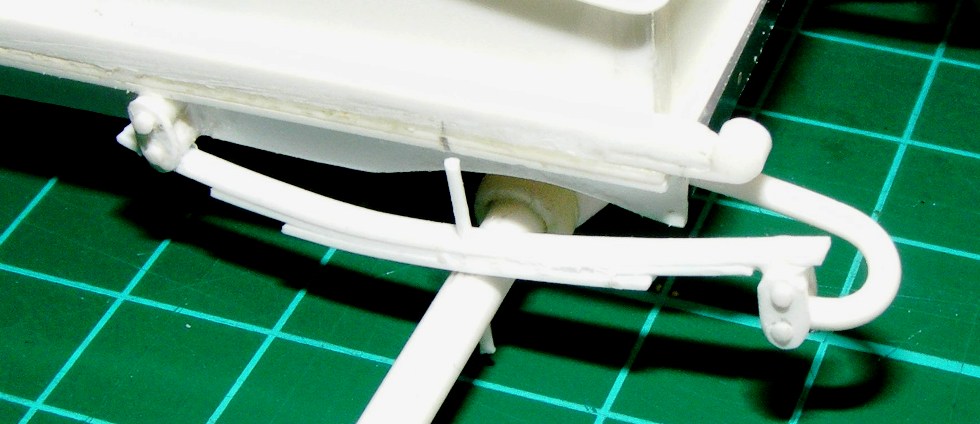
Securing the Front Springs to the Axle.
These springs are attached at the forward ends to the dumbirons and at the rearward ends by shackles located directly beneath the mudguard stay location holes in the Chassis beams. Each shackle consists of two plates, formed from 5mm lengths of strip sanded to an oval shape, sandwiching two 2mm lengths of tube. Rod is inserted through the plates and tube and the protruding ends are cut off leaving sufficient to represent the retaining pin heads.
With the springs secured by their centre post the top retaining plates were fitted with the central post passing behind the axle beam and the lower plate added. With the four bolts (plastic rod) inserted through the plates the axle became sandwich between the plates and the axle position was adjusted by sliding it sideways. When the correct position was attained the units were secured and the protruding rod ends cut back leaving only sufficient to represent retaining nuts.

The Rear Springs.
The rear spring were constructed in the same way as the front springs but the method of attachment is unusual as the forward end is ‘hung’ conventionally from the shackle while the rearward end is ‘supported’ on top of shackle.
The hangers protrude from beneath the rear floor and were formed by bending Evergreen extruded rod immersed in hot water until pliable then placed in a simple jig and left to cool. The centre pins pass through the rear axle to locate the springs.
Only one plate is used each side above the spring locating it to the axle.
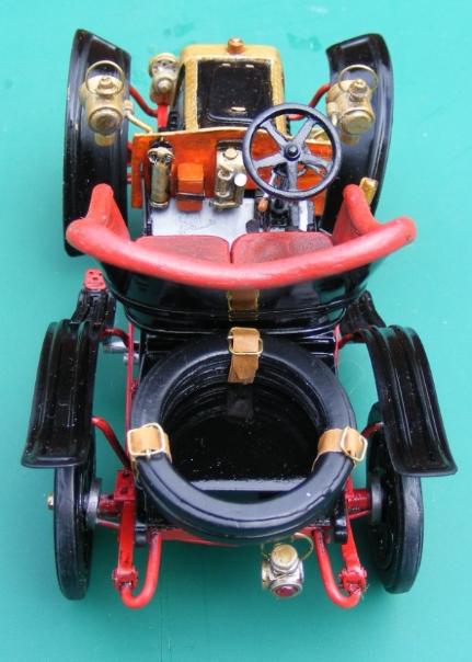
Transmission and rear axle
This is an unusual design with the rear axle being ‘off-set’ although the transmission shaft runs centrally. The transmission was constructed to form one unit, but in individual parts to facilitate assembly with the starting handle locating through the chassis cross member, into the (tubular) transmission shaft which in turn passes through the engine block to the rear mounted clutch housing and then on and into the ‘off-centre’ differential casting on the rear axle, All the items were constructed from Evergreen rod and tube.

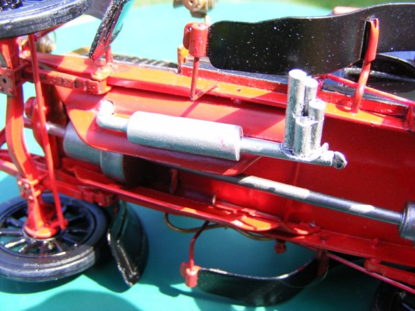
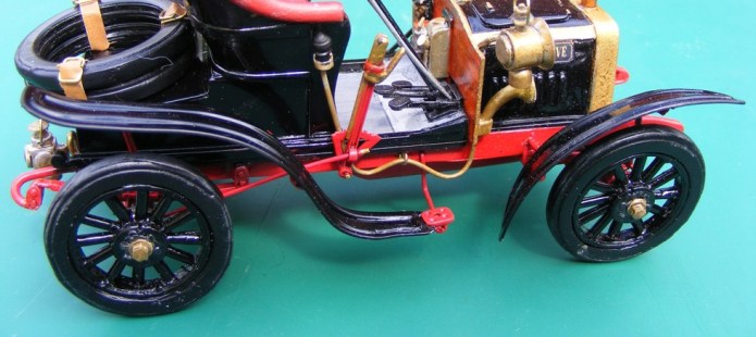
On ‘Genevieve’ The exhaust system included, in addition to the bulb horn, a whistle and varying references show a 3 and a 4 pipe instrument operated by a chain attached to the steering column and closing a flap on the end of the exhaust pipe. The whistle is attached at the end of the exhaust pipe that locates to the engine through a hole in the shroud.
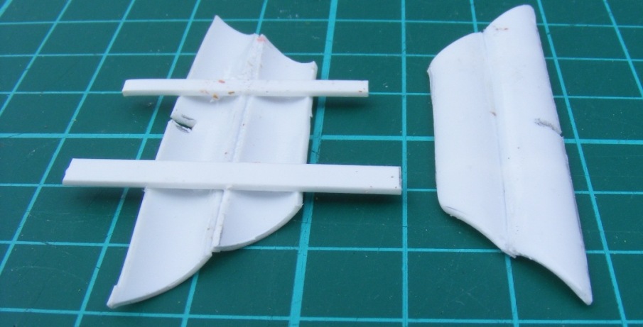
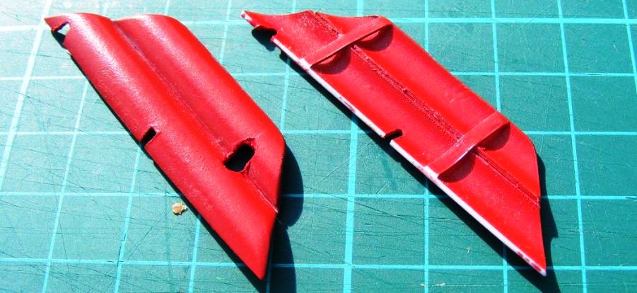
Another unusual feature of the car was the protective engine shrouds fitted below the chassis. These were made with Evergreen 1/2in. 236 tube quartered, shaped and supported on two strips of plastic from my ‘scraps box’. The holes and cut-out notches are to accept the exhaust pipe and chassis cross members.
Wheels and tyres.
It was necessary to make the wheels now so as to establish the shape and length of the mudguard supports.
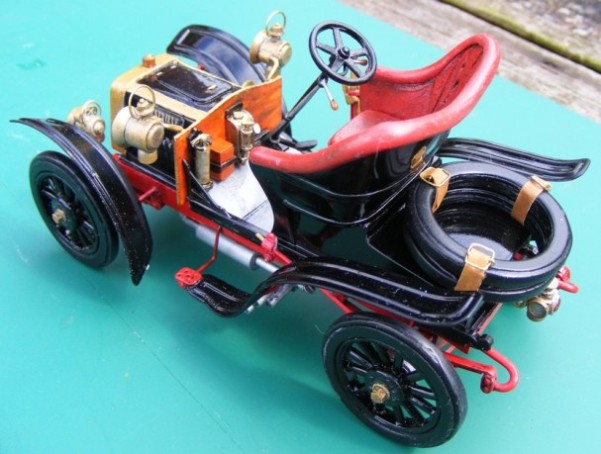
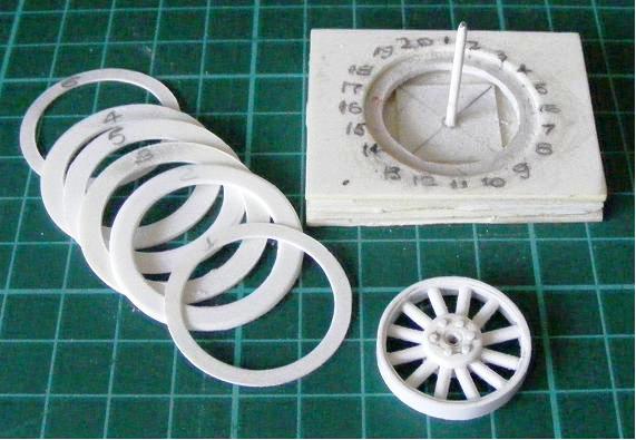
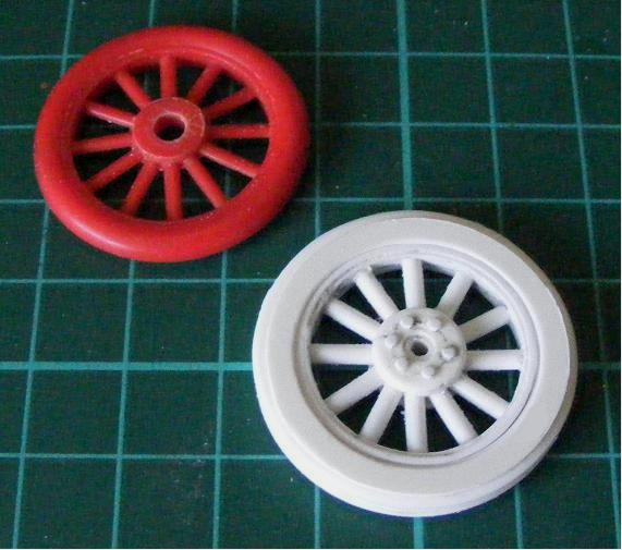
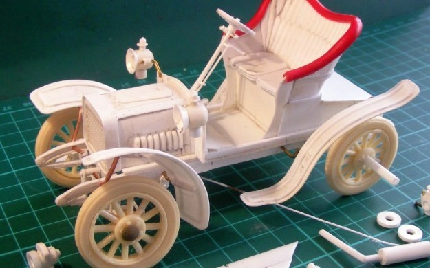
Rod decided to make a detailed wheel with a separate walled tyre in preference to the simple wheel and balloon tyre as on the original AIRFIX kit, the difference is obvious from the photos. The tyre was made up of several plasticard rings, the outer ones being slightly smaller in diameter to give the walled tyre profile, then moulded separately to allow for the casting of the two spare tyres. Most readers will be ‘Au fait’ with moulding and casting methods and materials, but for any modellers who have yet to venture into this field I suggest you contact Sylmasta at www.sylmasta.com who’s staff I have found to be very helpful and the product is simple to use and produces good results.

When attached to the model the spares tyres had masking tape straps and brass wire buckles added.
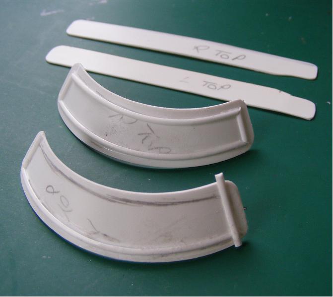
Mudguards.
The front mudguards are flared and it is not a simple job to cut them from flat sheet, but these are the notes I made when marking them out . 1 Draw a horizontal line 13 cm in length. 2.Mark the centre point of the line. 3. Set a compass to 65 mm, place point on centre mark and draw an arc traversing from end to end of the horizontal line. 4. Reset compass to 50 mm and from the centre point draw a second arc within the first one. 5. From centre point make a mark on each arc at an angle of 600 from the horizontal base line centre point, join the marks on the arcs and this will give you a curved pattern for the front mudguards.
The raised rib on the mudguards is represented with half-round Evergreen strip cut to length, chamfered at the corners and finally sanded down.
The mudguards were attached by brass wire supports, shaped and then inserted into pre-drilled holes in the chassis. Attachment to the mudguard was by sanding a flat face on short lengths of tube and cementing the flat surface to the mudguard underside. The back mudguards were similarly attached, but not being flared were drawn out as per the drawing. Obtaining the correct stance and dihedral is not a simple matter.
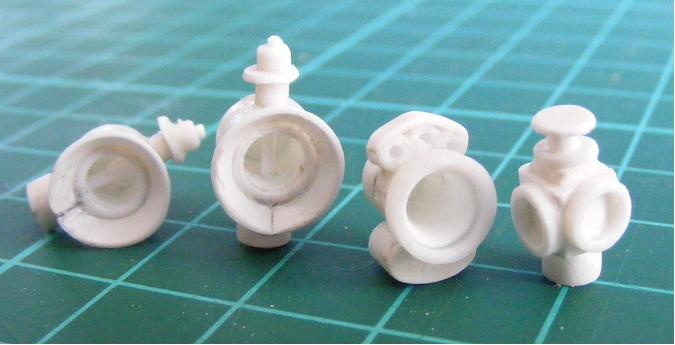
Instruments and controls.
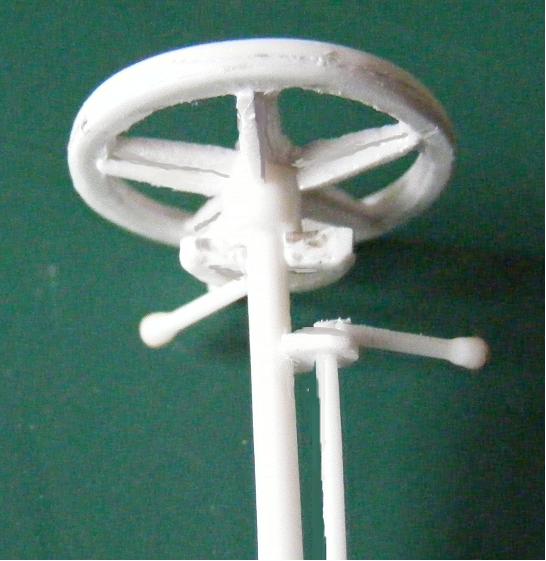
The dashboard carries a fire extinguisher, accessories box and the oil tank with pump, sight glad and gauge. Protruding from the lower right corner are the three foot pedals. On the steering column is the wheel, advance/retard and gear controls and to the drivers right attached to the outside of the body are the handbrake lever and quadrant and the horn bulb.
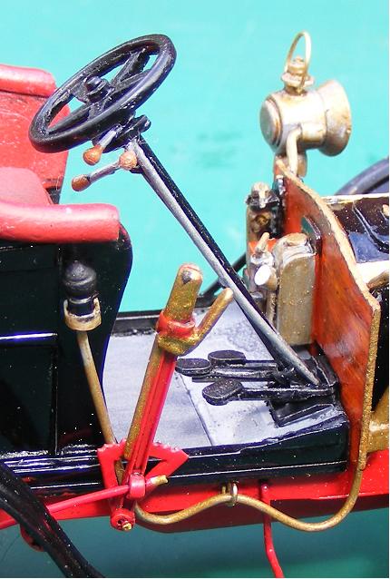
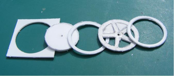
The 5-spoke steering wheel was made by cutting three circles from plasticard sheet and marking out the spokes on one, the remaining two had the centres removed to provide the rims. The spoke ring was then sandwiched between the two rim rings and elongated triangle of Evergreen strip were added beneath the spokes. The levers are plastic rod dipped in super glue to form the knob end and left to set. The material for most of these items came from the ‘scrap box’.
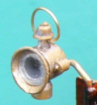
Lamps and fittings.
All the lamps are made with Evergreen rod, tube and strip and comprise seven or more component individual parts.
We hope that you can see how scratch building isn't as worrying as many people think it is. Just take your time keep trying, see the shapes and build thim bit by bit.
Just to finish off, here's a few more pictures of the finished model.